XYZ's of Oscilloscopes

Oscilloscope Types
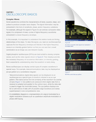
Electronic equipment can be classified into two categories: analog and digital. Analog equipment works with continuously variable voltages, while digital equipment works with discrete binary numbers that represent voltage samples. A conventional phonograph is an analog device, while a CD player is a digital device. Oscilloscopes can be classified similarly – as analog and digital types. In contrast to an analog oscilloscope, a digital oscilloscope uses an analog-to-digital converter (ADC) to convert the measured voltage into digital information. It acquires the waveform as a series of samples, and stores these samples until it accumulates enough samples to describe a waveform. The digital oscope then reassembles the waveform for display on the screen, as shown in Figure 11.
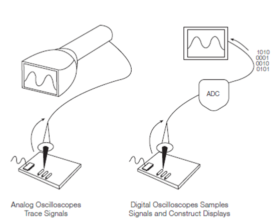
Figure 11: Analog oscilloscopes trace signals, while digital oscilloscopes sample signals and construct displays.
Types of Digital Oscilloscopes
Digital oscilloscopes can be classified into four types:
- Digital storage oscilloscopes (DSO)
- Digital phosphor oscilloscopes (DPO)
- Mixed signal oscilloscopes (MSO)
- Digital sampling oscilloscopes
This chapter describes these types of digital oscilloscopes in detail to help you zero in on the type of oscilloscope that’s right for your needs. If you need to go back to oscilloscope basics, check out our post entitled, "What is an oscilloscope?"
Digital Storage Oscilloscopes (DSO)
A conventional digital oscilloscope is known as a digital storage oscilloscope (DSO). Its display typically relies on a raster-type screen rather than the luminous phosphor found in older analog oscilloscopes.
DSOs allow you to capture and view events that may happen only once, known as transients. Because the waveform information exists in digital form as a series of stored binary values, it can be analyzed, archived, printed, and otherwise processed, within the oscope itself or by an external computer.
The waveform need not be continuous; it can be displayed even when the signal disappears. Unlike analog oscilloscopes, DSOs provide permanent signal storage and extensive waveform processing. However, DSOs typically have no real-time intensity grading. Therefore they cannot express varying levels of intensity in the live signal.
Some of the subsystems in DSOs are similar to those in analog oscilloscopes. However, DSOs contain additional data-processing subsystems that are used to collect and display data for the entire waveform. A DSO employs a serial-processing architecture to capture and display a signal on its screen, as shown in Figure 12.
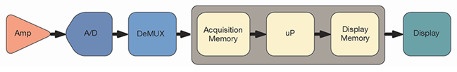
Figure 12: The serial-processing architecture of a digital storage oscilloscope (DSO).
Serial-processing Architecture
Like an analog oscilloscope, a DSO’s first (input) stage is a vertical amplifier. Vertical controls allow you to adjust the amplitude and position range at this stage. Next, the analog to digital converter (ADC) in the horizontal system samples the signal at discrete points in time and converts the signal’s voltage at these points into digital values called sample points. This process is referred to as digitizing a signal.
The horizontal system’s sample clock determines how often the ADC takes a sample. This rate is referred to as the sample rate and is expressed in samples per second (S/s).
The sample points from the ADC are stored in acquisition memory as waveform points. Several sample points may comprise one waveform point. Together, the waveform points comprise one waveform record. The number of waveform points used to create a waveform record is called the record length. The trigger system determines the start and stop points of the record.
The DSO’s signal path includes a microprocessor through which the measured signal passes on its way to the display. This microprocessor processes the signal, coordinates display activities, manages the front panel controls, and more. The signal then passes through the display memory and is displayed on the oscilloscope screen.
Depending on the capabilities of an oscilloscope, additional processing of the sample points may take place, which enhances the display. Pre-trigger may also be available so you can see events before the trigger point. Most digital oscilloscopes also provide a selection of automatic parametric measurements, simplifying the measurement process.
DSOs provide high performance in a single-shot, multi-channel instrument (Figure 13). They are ideal for low repetition-rate or single-shot, high-speed, multichannel design applications. In the real world of digital design, an engineer usually examines four or more signals simultaneously, making the DSO a critical companion.
Figure 13: The digital storage oscilloscope delivers high-speed, single-shot acquisition across multiple channels, increasing the likelihood of capturing elusive glitches and transient events
Digital Phosphor Oscilloscopes (DPO)
The digital phosphor oscilloscope (DPO) offers a new approach to oscilloscope architecture. This architecture enables it to deliver unique acquisition and display capabilities to accurately reconstruct a signal. While a DSO uses a serial-processing architecture to capture, display, and analyze signals, a DPO employs a parallel processing architecture to perform these functions (Figure 14).
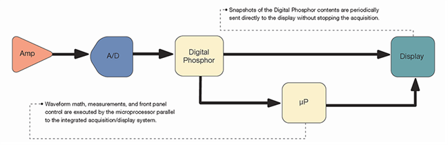
Figure 14: The parallel-processing architecture of a digital phosphor oscilloscope (DPO).
The DPO architecture dedicates unique ASIC hardware to acquire waveform images, delivering high waveform capture rates, resulting in a higher level of signal visualization. This performance increases the probability of witnessing transient events that occur in digital systems, such as runt pulses, glitches and transition errors, and enables additional analysis capability.
Parallel-processing Architecture
A DPO’s first (input) stage is similar to that of an analog oscilloscope—a vertical amplifier—and its second stage is similar to that of a DSO—an ADC. But, the DPO differs significantly from its predecessors following the analog-to-digital conversion.
For any oscilloscope—analog, DSO, or DPO—there is always a hold-off time during which the instrument processes the most recently acquired data, resets the system, and waits for the next trigger event. During this time, the oscilloscope is blind to all signal activity. The probability of seeing an infrequent or low repetition event decreases as the hold off time increases.
It is impossible to determine the probability of capture by simply looking at the display update rate. If you rely solely on the update rate, it is easy to make the mistake of believing that the oscilloscope is capturing all pertinent information about the waveform when, in fact, it is not.
The DSO processes captured waveforms serially. The speed of its microprocessor is a bottleneck in this process because it limits the waveform capture rate. The DPO rasterizes the digitized waveform data into a digital phosphor database. Every 1/30th of a second—about as fast as the human eye can perceive it—a snapshot of the signal image that is stored in the database is pipelined directly to the display. This direct rasterization of waveform data, and direct copy to display memory from the database, removes the data-processing bottleneck inherent in other architectures. The result is an enhanced “real-time” and lively display update. Signal details, intermittent events, and dynamic characteristics of the signal are captured in real-time. The DPO’s microprocessor works in parallel with this integrated acquisition system for display management, measurement automation, and instrument control, so that it does not affect the oscilloscope’s acquisition speed.
A DPO faithfully emulates the best display attributes of an analog oscilloscope, displaying the signal in three dimensions: time, amplitude, and the distribution of amplitude over time. All in real-time.
Unlike an analog oscilloscope’s reliance on chemical phosphor, a DPO uses a purely electronic digital phosphor that’s actually a continuously updated database. This database has a separate “cell” of information for every single pixel in the oscilloscope’s display. Each time a waveform is captured—in other words, every time the oscilloscope triggers—it is mapped into the digital phosphor database’s cells. Each cell that represents a screen location and is touched by the waveform is reinforced with intensity information, while other cells are not. Thus, intensity information builds up in cells where the waveform passes most often.
When the digital phosphor database is fed to the oscilloscope’s display, the display reveals intensified waveform areas, in proportion to the signal’s frequency of occurrence at each point, much like the intensity grading characteristics of an analog oscilloscope. The DPO also allows the display of the varying frequency-of-occurrence information on the display as contrasting colors, unlike an analog oscilloscope. With a DPO, it is easy to see the difference between a waveform that occurs on almost every trigger and one that occurs, say, every 100th trigger.
A DPO break down the barrier between analog and digital oscilloscope technologies. They are equally suitable for viewing high and low frequencies, repetitive waveforms, transients, and signal variations in real-time. Only a DPO provides the Z-axis (intensity) in real-time that is missing from conventional DSOs.
A DPO is ideal for those who need the best general purpose design and troubleshooting tool for a wide range of applications (Figure 15). A DPO is exemplary for advanced analysis, communication mask testing, digital debug of intermittent signals, repetitive digital design. and timing applications.
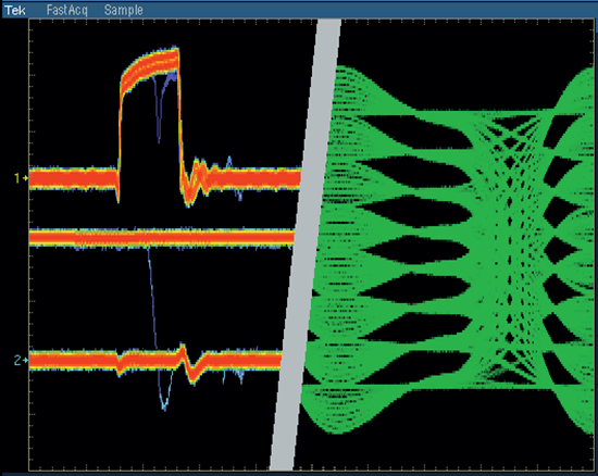
Figure 15: Some DPOs can acquire millions of waveform in just seconds, significantly increasing the probability of capturing intermittent and elusive events and revealing dynamic signal behavior.
Mixed Domain Oscilloscopes (MDO)
A mixed domain oscilloscope (MDO) combines an RF spectrum analyzer with a MSO or DPO to enable correlated views of signals from the digital, analog, to RF domains. For example, the MDO allows you to view time-correlated displays of protocol, state logic, analog, and RF signals within an embedded design. This dramatically reduces both the time to insight and the measurement uncertainty between cross domain events.
Understanding the time delay between a microprocessor command and a RF event within an embedded RF design simplifies test setups and brings complex measurements to the bench. For embedded radios, such as the Zigbee design shown in Figure 16, you can trigger on the turn-on of the RF event and view the command line latency of the microprocessor controller decoded SPI control lines, the drain current and voltage during turn-on, and any spectral events that result. In one display, you now have a time-correlated view of all the domains of the radio: protocol (digital), analog, and RF.
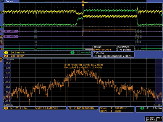
Figure 16: Time-correlated display of a Zigbee radio's microprocessor SPI (MOSI) and (MISO) control lines, with measurements of drain current and voltage to the radio IC and the spectrum during turn-on.
Mixed Signal Oscilloscopes (MSO)
The mixed signal oscilloscope (MSO) combines the performance of a DPO with the basic functionality of a 16-channel logic analyzer, including parallel/serial bus protocol decoding and triggering.
The MSO's digital channels view a digital signal as either a logic high or logic low, just like a digital circuit views the signal. This means as long as ringing, overshoot and ground bounce do not cause logic transitions, these analog characteristics are not of concern to the MSO. Just like a logic analyzer, a MSO uses a threshold voltage to determine if the signal is logic high or logic low.
The MSO is the tool of choice for quickly debugging digital circuits using its powerful digital triggering, high-resolution acquisition capability, and analysis tools. The root cause of many digital problems is quicker to pinpoint by analyzing both the analog and digital representations of the signal, as shown in Figure 17, making an MSO ideal for verifying and debugging digital circuits.
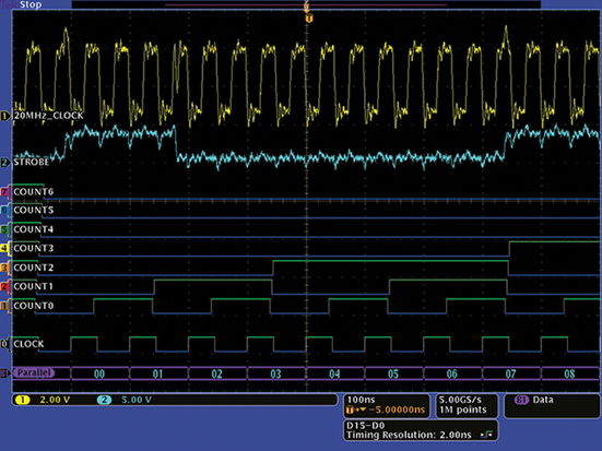
Figure 17: The MSO provides 16 integrated digital channels, enabling the ability to view and analyze time-correlated analog and digital signals.
Digital Sampling Oscilloscopes
In contrast to the digital storage and DPO architectures, the architecture of the digital sampling oscilloscope reverses the position of the attenuator/ amplifier and the sampling bridge (Figure 18). The input signal is sampled before any attenuation or amplification is performed. A low bandwidth amplifier can then be used after the sampling bridge because the signal has already been converted to a lower frequency by the sampling gate, resulting in a much higher bandwidth instrument.
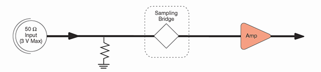
Figure 18: Architecture of a digital sampling oscilloscope
The tradeoff for this high bandwidth, however, is that the sampling oscilloscope’s dynamic range is limited. Since there is no attenuator/amplifier in front of the sampling gate, there is no facility to scale the input. The sampling bridge must be able to handle the full dynamic range of the input at all times. Therefore, the dynamic range of most sampling oscilloscopes is limited to about 1 V peak-to-peak. Digital storage and DPOs, on the other hand, can handle 50 to 100 volts.
In addition, protection diodes cannot be placed in front of the sampling bridge, as this limits the bandwidth. This reduces the safe input voltage for a sampling oscilloscope to about 3 V, as compared to 500 V available on other oscilloscopes.
When measuring high-frequency signals, the DSO or DPO may not be able to collect enough samples in one sweep. A digital sampling oscilloscope is an ideal tool for accurately capturing signals whose frequency components are much higher than the oscilloscope’s sample rate (Figure 19). This oscilloscope is capable of measuring signals of up to an order of magnitude faster than any other oscilloscope. It can achieve bandwidth and high-speed timing ten times higher than other oscilloscopes for repetitive signals. Sequential equivalent-time sampling oscilloscopes are available with bandwidths to 80 GHz.
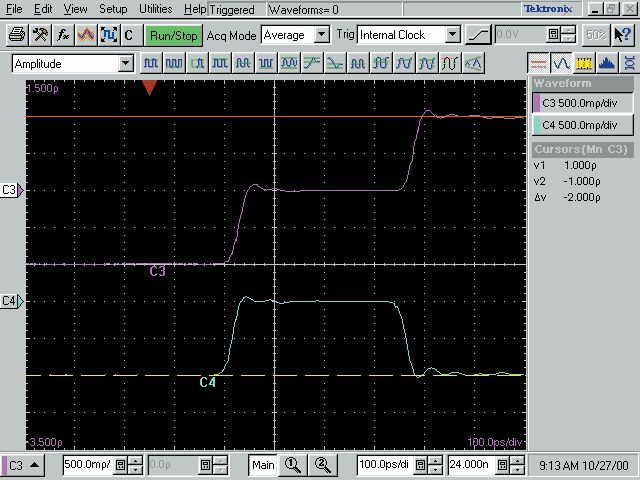
Figure 19: Time domain reflectometry (TDR) display from a digital sampling oscilloscope.