Introduction
Comprehensive characterization of high-speed links such as PCI Express® require performing measurements of the Transmitter (Tx) and Receiver (Rx) across multiple differential lanes for the link under test. This presents challenges for a fully automated test environment given the need to physically change coaxial connections between the different channels. Incorporating an RF switch matrix allows multi-lane testing with physical connection changes and enables automation software testing. This paper describes how to expand the test environment for automated multi-lane testing using an RF switch from Mini-Circuits® and can be extended to other RF switch modules and technologies.
PCI Express ports typically come in lane widths of x1, x4, x8, and x16 which leads to challenges for fully automated Tx or Rx testing. Including an RF switch in the test channel enables multi-lane testing without excessive cable changes to the DUT and test equipment. Care must be taken to minimize the electrical impact of the RF switch and ensure the testing is true to the specification requirements or validation test plan. This paper describes using the MiniCircuits RF switch(s) for Gen5 (32 GT/s) multi-lane testing and will provide some general guidance for setup, automated testing, and advice on commonly encountered challenges.
This document will focus on the RF switch configurations required for x16 testing, but lower price point models can be recommended from your local field support teams as needed. These switch models will support up to 18 lanes (PCIe max is typically x16) and will support the lower lane counts as well. Rigid cables are recommended to establish the fixed connections between different switch components and are available from Mini-Circuits upon request. Diagrams for CEM testing are presented initially, but the techniques also apply to BASE testing with the corresponding diagrams shown in the final section of this white paper.
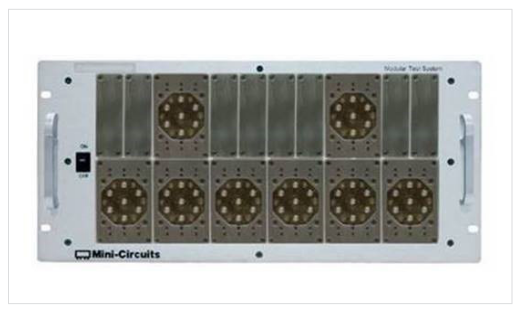
The ZTM2-8SP6T-40 modular switch matrix with 8 x 40GHz terminated SP6T mechanical switches is shown in figure 1. This configuration will support up to 18 lanes. Phase matched cables are recommended for the fixed connection branching between adjacent 40 GHz relays. Termination of 50 Ohms will be present when the relay is not switched for a thru connection.
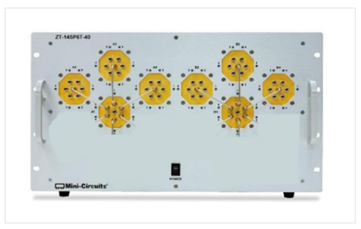
The ZT-8SP6T-40 4U/5U switch matrix with 8 x 40GHz terminated SP6T mechanical switches is shown in figure 2. This configuration will support up to 18 lanes. Rigid cables are recommended (included in image) for the fixed connection branching between adjacent 40 GHz switches. The orientation of the switch components in this matrix maintains a similar electrical path length between all input and outputs. This is especially appealing for multilane Rx testing to minimize path-to-path differences between calibration and test. Termination of 50 Ohms will be present when the relay is not switched for a thru connection.
RF Switch Matrix – Gen5 Tx Testing
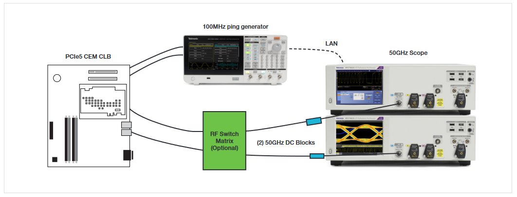
PCIe Gen5 devices (System Host or Add-in card) will exhibit different transmitter performance across a multi-lane port. Validation of all lanes is common to fully characterize the link and identify issues with silicon performance, excessive near-end or far-end crosstalk, or layout defects. Utilizing an RF switch (figure 3) in the test setup enables multi-lane Tx validation without continuous connection changes by an engineer or technician. The connections will be similar for 32 GT/s Base Tx testing (see figure 10).
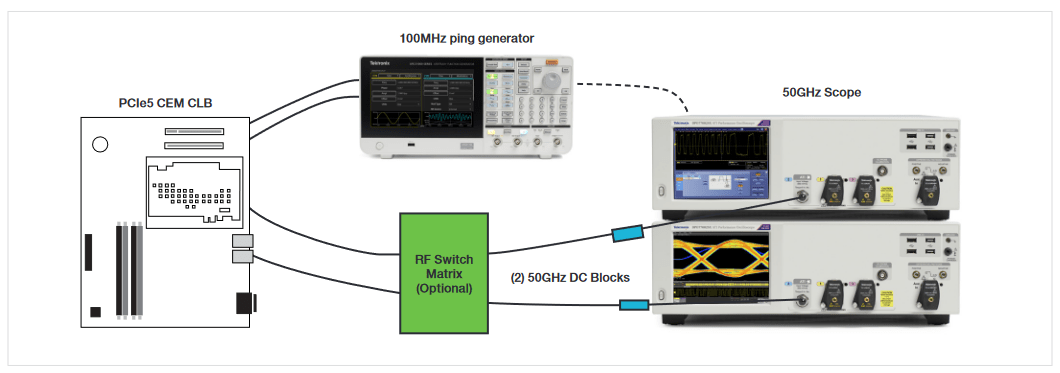
A system host configuration will require a compliance load board (CLB) plugged into the DUT’s CEM connector and cables from each lane to the RF switch. An add-in card configuration will be similar except the DUT will plug into a compliance base board (CBB). A single pair of cables connects the terminated switch matrix back to the 50 GHz scope. An instrument such as an arbitrary function generator (AFG) allows automation of the 100MHz burst signal required to cycle the DUT through various data rates and patterns for different transmitter measurements.
Each connection made in the switch setup is important. It is not recommended to cascade more than two relays in series for 32 GT/s Tx testing due to insertion loss. Use of 1-meter 2.92mm cables (e.g. Tektronix PN: PMCABLE1M) is recommended between the DUT and RF switch and use of shorter 0.5-meter 2.92mm cables (e.g. Tektronix PN: 174-6663-01) is recommended between the RF switch and scope inputs. The scope differential fast edge can be used to perform automated channel-to-channel deskew with the TekExpress software.
All cables, relays, and PCB’s in the channel should be matched within +/- 1ps each between the positive and negative signal paths.
Maintaining 50 Ohm (100 Ohm differential) connections in/out of the RF switch will minimize reflections within the channel, but some insertion loss will be introduced. The 32 GT/s signal quality test does not require a physical variable ISI board (required for Gen4 test), so the additional channel and package loss are required to be embedded on the scope. Test fixture characterization (described in Appendix B of the 5.0 PHY Test Specification) including the RF switch should be performed. Essentially a lower loss filter file will be selected to achieve worst case add-in card loss (when testing a system host) or worstcase system loss (when testing an add-in card). The SignalCorrect solution from Tektronix may be used to verify channel losses including RF switch matrix versus using an expensive VNA.
Scattering parameter (s-parameter) based de-embedding may be used to remove the impact of the RF switch insertion loss. De-embedding introduces complexity for the gain of accuracy, but the impact of noise amplification must be considered as well. If phase matched RF cables are used between relay-to-relay connections, only small electrical differences will exist channel-to-channel. Custom channel s-parameter files can be considered if these differences are considered impactful to the measurement. The s-parameter files may be captured using SignalCorrect or a Vector Network Analyzer (VNA). Alternatively, nominal s-parameter files may be provided by the Tektronix field team.
RF Switch Matrix – Gen5 Rx Testing
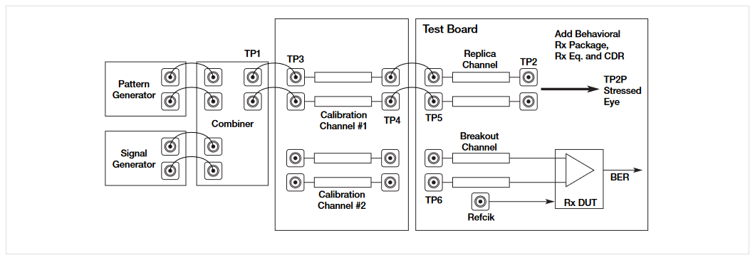
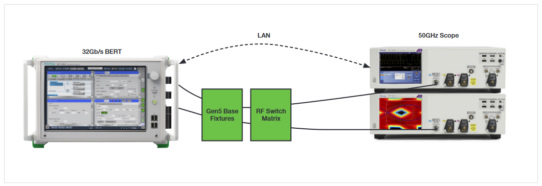
PCIe Gen5 devices (systems or add-in cards) receivers are tested with a finely calibrated stressed eye signal. This "worst case" signal is established through multiple calibration steps at a reference plane (without a channel) and with a "worst case" channel required to be between 34 dB & 37 dB @ 16 GHz. Understanding how to incorporate a terminated RF switch into the calibration of this signal for Rx testing and then test the DUT across a multilane link will be discussed in this section.
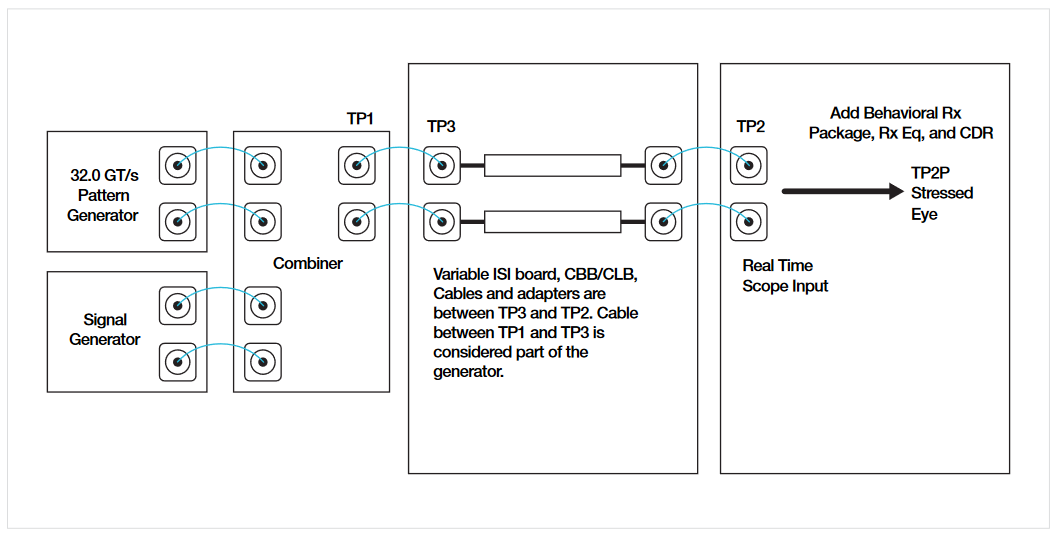
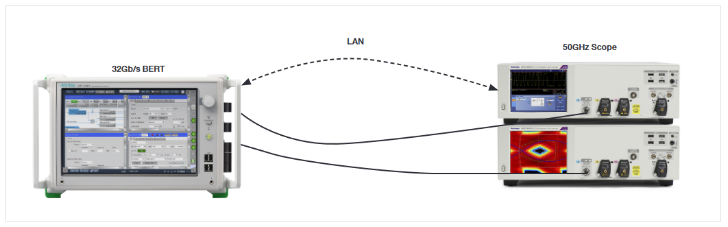
Calibration of amplitude, Tx equalization, random jitter, and sinusoidal jitter at the TP3 test point requires a direct connection between the Anritsu MP1900A BERT PPG and the Tektronix 50 GHz scope. It is recommended to use 1-meter 2.92mm cables (e.g. Tektronix PN: PMCABLE1M) for this connection. The TP3 calibration connection is shown in figure 5 without the RF switch included during this step. Since there will be some electrical channel length differences introduced by the RF switch it is recommended not to include this impact before the TP3 reference plane.
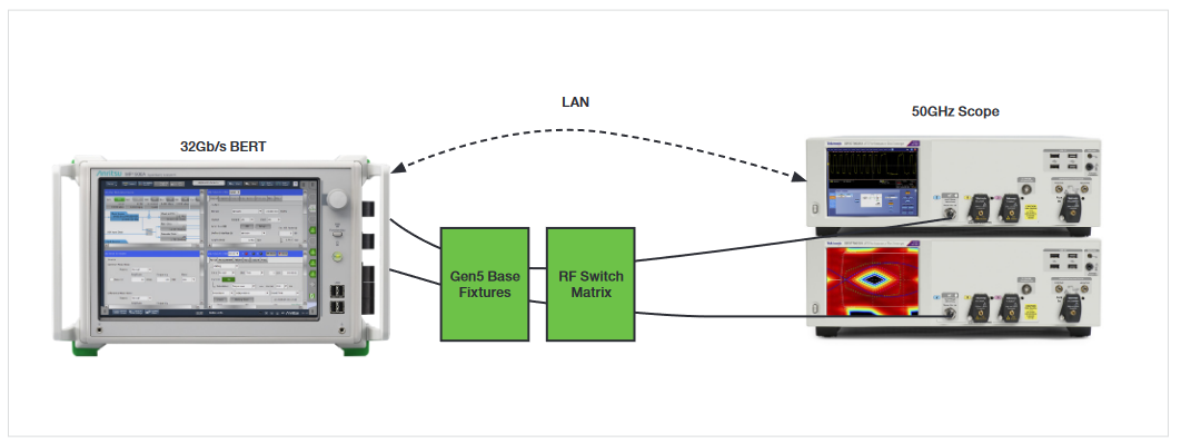
Calibration of the crosstalk term using differential mode interference (DMI), common mode interference (CMI), and the final stressed eye diagram is performed at TP2P. This test point comes after TP2 (physical channel between the BERT & Scope), but TP2P includes the package embedding and impact of Rx equalization and clock recovery. The addition of the RF switch for TP2 calibration is shown in figure 6 where the switch is introduced after the test fixtures (Base or CEM). At this point the engineer must decide if a single TP2 calibration is needed (recommended for ZT-8SP6T-40 4U/5U) or if two or more TP2 calibrations are needed (advisable to account for the different electrical path lengths of the ZTM2-8SP6T-40). It is not recommended to cascade more than two relays for 32 GT/s stressed eye calibration.
It is recommended to use 1-meter 2.92mm cables (e.g. Tektronix PN: PMCABLE1M) between the BERT and RF switch and shorter 0.5-meter 2.92mm cables (e.g. Tektronix PN: 174-6663-01) between the RF switch and scope. The scope differential fast edge can be used to perform automated channel-to-channel deskew with the TekExpress software.
All cables, relays, and PCBs in the channel should be matched within +/- 1ps each between the positive and negative signal paths.
Maintaining 50 Ohm (100 Ohm differential) connections in/out of the RF switch will minimize reflections within the channel, but some insertion loss will be introduced. The 32 GT/s signal quality test does not require a physical variable ISI board (required for Gen4 test), so the additional channel and package loss are required to be embedded on the scope. Test fixture characterization (described in Appendix B of the 5.0 PHY Test Specification) including RF switch should be performed. Essentially a lower loss filter file will be selected to achieve worst case add-in card loss (when testing a system host) or worst-case system loss (when testing an add-in card). The SignalCorrect solution from Tektronix may be used to verify channel losses including the RF switch matrix versus using an expensive VNA.
Scattering parameter (s-parameter) based de-embedding may be used to remove the impact of the RF switch insertion loss. De-embedding introduces complexity for the gain of accuracy, but the impact of noise amplification must be considered as well. If phase matched RF cables are used between relay-to-relay connections, only small electrical differences will exist channel-to-channel. Custom channel s-parameter files can be considered if these differences are considered impactful to the measurement. The s-parameter files may be captured using SignalCorrect or a VNA. Alternatively, nominal s-parameter files may be provided by the Tektronix field team.
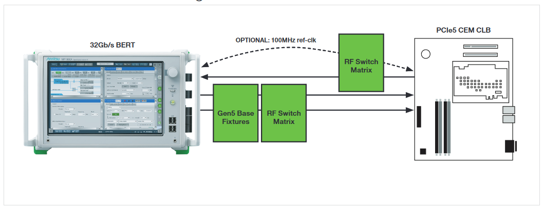
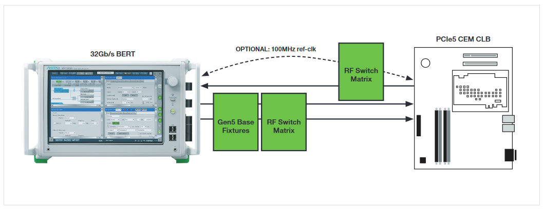
Receiver testing using the calibrated stressed eye signal at 32 GT/s across multiple lanes requires two RF switch matrixes as shown in figure 7. When the link is a x8 or lower lane count a single RF switch matrix may be considered. The signal from the Anritsu MP1900A PPG must be distributed to all PCIe lanes. The device will be in loopback, so the digitized signal will be transmitted back out through the Tx pins and switched back to a single input at the BERT’s error detector. Many 32 GT/s capable systems will exhibit a high loss back channel to the error detector and will require an external re-driver to equalize the signal for detection by the test equipment. Introduction of an RF switch may force the need for an external re-driver if one wasn’t already required. The connections will be similar for 32 GT/s Base Rx LEQ testing (see figure 13).
It is recommended to use 1-meter 2.92mm cables (e.g., Tektronix PN: PMCABLE1M) between the BERT and RF switch and shorter 0.5-meter 2.92mm cables (e.g., Tektronix PN: 174-6663-01) between the RF switch and scope. The shortest 2.92mm cables between the DUT Tx and error detector should be considered.
How to Establish Communication with Mini-Circuits
TekExpress TX automation software (See datasheet here.) offers built-in control of Mini-Circuits switch matrix during automated TX test. This section is provided to guide users in developing their own automation software to control the RF switch during either TX or RX testing.
How to connect: There are two possible communication methods with the Mini-Circuits switch:
- USB using dll (dynamic link library).
- Ethernet HTTP requests
USB Connection:
- Connect a USB device cable from the oscilloscope to a Mini-Circuits RF switch.
- Download "mcl_ZTM2_NET45.dll" ( See "Software" here. )
- Move the DLLs
- Copy the "ModularZT_NET45.dll" to "C:\Windows\SysWOW64" if its 64bit OS.
- Copy the "ModularZT_NET45.dll" to "C:\Windows\System32" for 32bit OS.
- Send the following commands using iron python
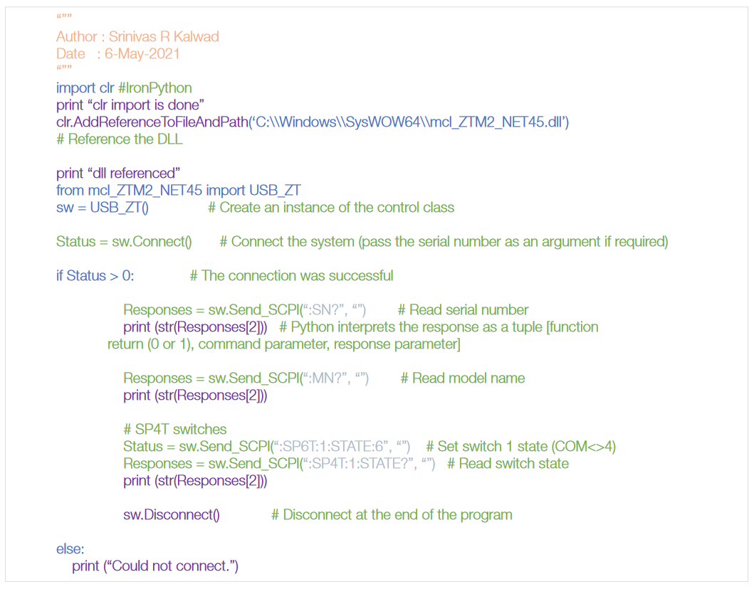
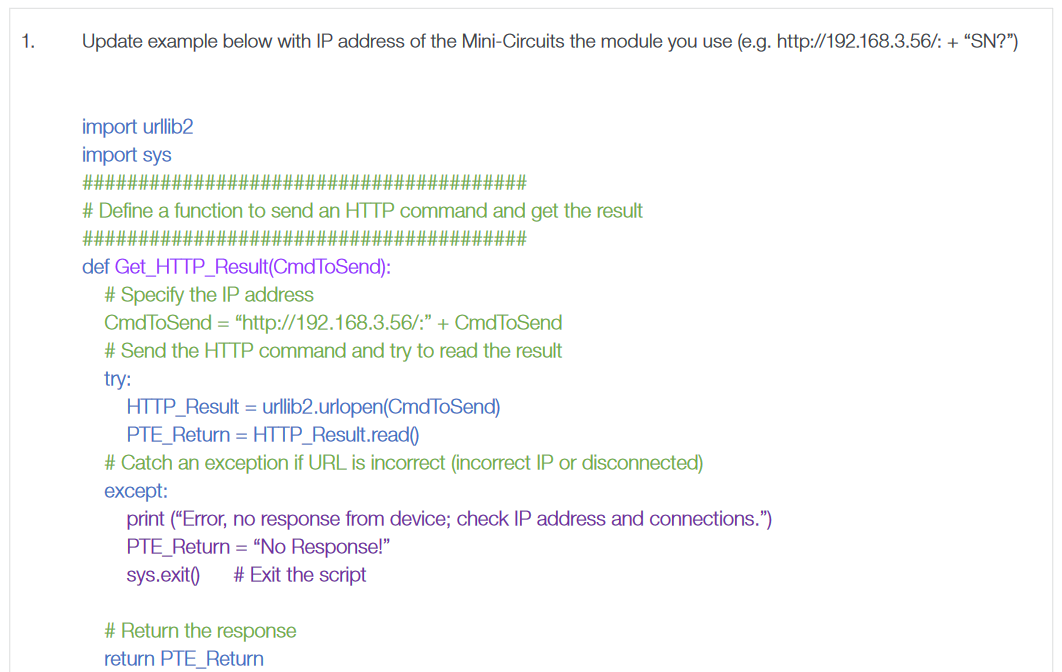
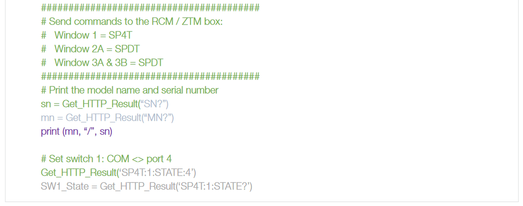
Ethernet HTTP requests:
It uses URllib2 python module to send and receive
BASE Calibration & Test Diagrams