Confirming Ride-through
Conformance for Grid-tied
Inverters with Automated
Oscilloscope Measurements
APPLICATION NOTE

Confirming Ride-through Conformance for Grid-tied Inverters with
Automated Oscilloscope Measurements
APPLICATION NOTE
Introduction
This Application Note
Standards have been developed to ensure compatibility
• Gives a basic overview of the rationale behind ride-
and mutual support between the grid and local, distributed
through measurements
energy systems. The protocols for ensuring compliance
of photovoltaic (PV), energy storage systems (ESS) and
• Describes an oscilloscope-based system for testing
grid-tied inverters (GTI) in general, may involve third
ride-through
party test houses, but it is important for designers to be
• Explains how special oscilloscope measurements
able to reliably measure ride-through and optimize ride-
can be used to validate an inverter’s low voltage
through performance using readily available tools such as
ride-through (LVRT) and high voltage ride-through
oscilloscopes.
(HVRT) performance
• Gives examples of low voltage ride-through and
The Evolution of Standards for
high voltage ride-through measurements
Grid-tied Inverters (GTIs)
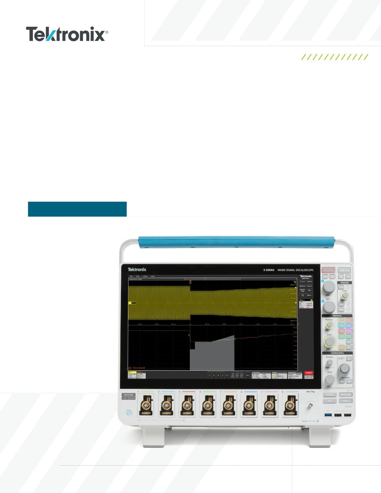
The instrument used in this application note is a
Distributed energy resources, such as photovoltaic (PV)
5 Series B Mixed Signal Oscilloscope equipped with
installations, energy storage systems, wind turbines
Advanced Power Measurement and Analysis software
and backup generators, can serve not only local loads,
(Option 5-PWR). A comparably-equipped 4 Series B MSO
but can also feed energy back onto the grid. Any time an
or 6 Series B MSO will operate almost identically.
energy source backfeeds the electrical power system, this
presents a hazard for technicians. Thus, early standards
that distributed energy resources meet ride-through
such as IEEE 1547-2003 focused on preventing “islanding”,
requirements that keep them delivering energy to the grid
in which a local source feeds back into an electrical
for specific voltage levels and times.
power system which has been disconnected from its main
PV and other GTIs must be capable of riding through voltage
generators. These standards mandated shutdown of the
disturbances-both low and high-without disconnecting
distributed resource after sensing a significant voltage
from the grid. This capability is categorized into:
sag or swell.
• Low Voltage Ride Through (LVRT)
As grid-tied inverters proliferated and began to offer more
• High Voltage Ride Through (HVRT)
capacity, engineers realized that quickly disconnecting
them from the grid in response to an undervoltage or
Key standards that specify ride-through limits include:
overvoltage event was suboptimal. Smart inverters could
• IEEE-1547-2018 Standard for Interconnecting
help to stabilize the grid and prevent cascading failures.
Distributed Resources with Electric Power Systems.
For example, having many photovoltaic (PV) systems
IEEE-1547.1-2020 covers testing methods. UL 1741 SB
disconnect from the grid in response to a voltage sag would
specifies testing procedures used for conformance.
decrease the available current in the system, worsening the
• EN 50549-1:2019 Requirements for generating plants
sag. This could result in a cascading effect. Alternatively,
to be connected in parallel with distribution networks
engineers realized that if the distributed systems could
- Part 1: Connection to a LV distribution network -
remain connected to the utility for some time during a
Generating plants up to and including Type B. EN 50549-
utility undervoltage event, they can contribute to grid
2 covers medium voltage networks.
stability. So in addition to controlling islanding behavior,
newer standards such as the IEEE-1547-2018 mandate
2 | WWW.TEK.COM
Confirming Ride-through Conformance for Grid-tied Inverters with
Automated Oscilloscope Measurements
APPLICATION NOTE
Test System Overview
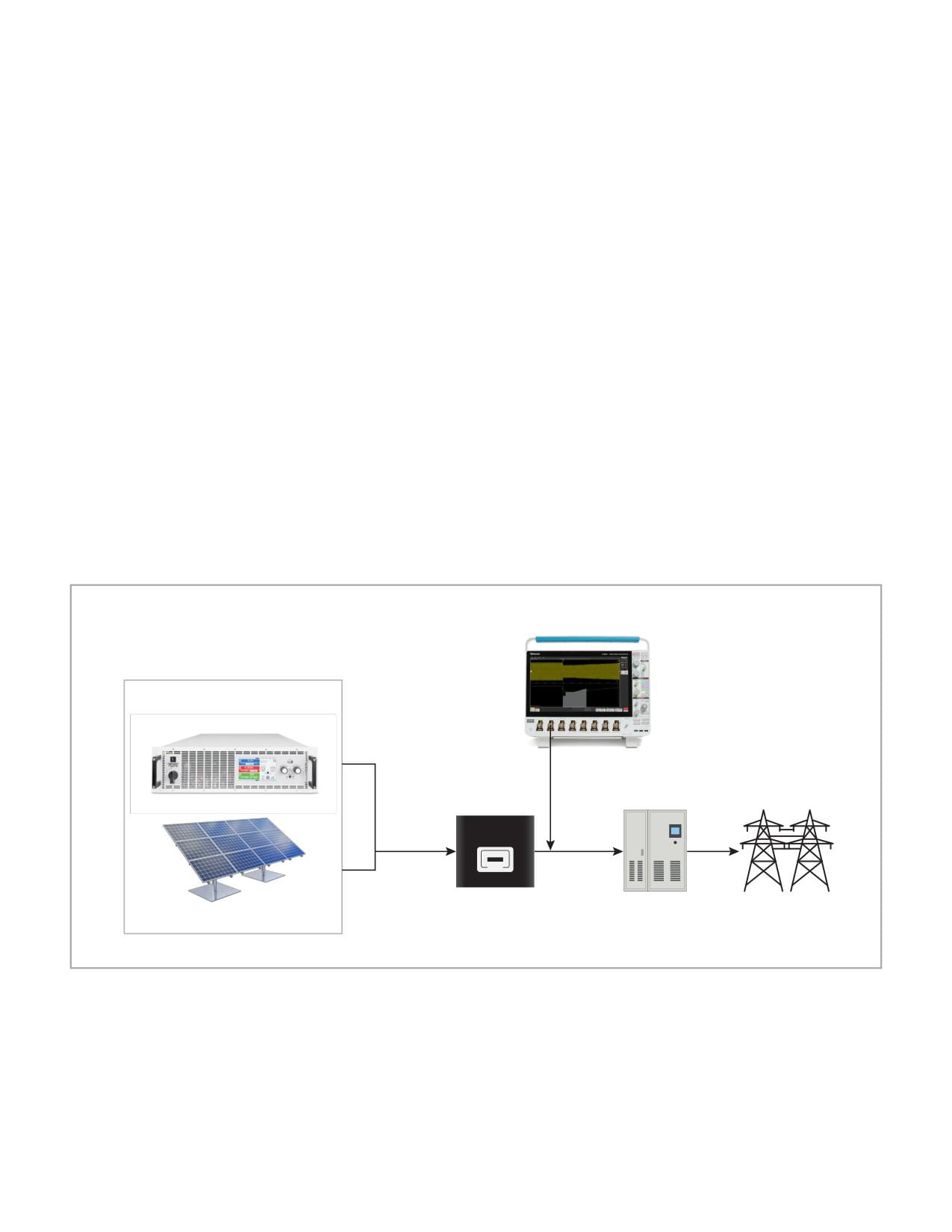
The device under test (DUT) is typically a bi-directional
In this application note, the 5 Series B MSO is equipped with
smart inverter. Figure 1 shows a typical setup for measuring
Advanced Power Measurement and Analysis software which
an inverter. A DC source may be used to simulate the output
enables automated ride-through measurements.
of the PV string, and a grid simulator is used to simulate
For measuring the output of the inverter, a high-voltage
undervoltage or overvoltage events. On the design or
differential probe is the best option. Differential probes
debugging bench, an autotransformer or Variac may also be
enable floating measurement and prevent ground currents
used to simulate grid events.
caused by earth connections.
Oscilloscopes, paired with high voltage differential probes,
• The THDP0200 is specified for up to 1500 V differential,
play a vital role in validation. In addition to validating ride-
600 VRMS Cat III. It provides 200 MHz bandwidth.
through measurements as described in this app note,
they enable:
• The THDP0100 is specified for up to 6000 V differential,
CAT III. It provides 100 MHz bandwidth.
1000 VRMS
• Capturing high-speed transient responses of inverters
• The TMDP0200 may be used for up to 750 V differential,
• Measuring harmonics, power quality and IQ variations
450 VRMS CAT I in test environments with limited
during ride-through events
available fault current. It provides 200 MHz bandwidth.
• Diagnosing switching behavior and control
Note that the single-ended passive probes that are included
loop dynamics
with the oscilloscopes should only be used for earth-
grounded measurements and may be rated for 300 VRMS CAT
II environments.
4/5/6 Series B MSO
PV Simulator or
Bi-Directional Power Supply
THDP0200/
THDP0100
Input
Output
Grid-tied Inverter
AC Grid Simulator/
Grid System
Solar Panel
Under Test
Auto Transformer
Figure 1. An example of a single-phase PV inverter test setup. The DC source simulates strings of solar panels and a grid simulator is tied to the grid side of the
inverter under test.
WWW.TEK.COM | 3
Confirming Ride-through Conformance for Grid-tied Inverters with
Automated Oscilloscope Measurements
APPLICATION NOTE
• Category III supports the grid during severe voltage dips
Ride-Through
and surges. This is critical for maintaining grid stability
Measurements Explained
in high-DER penetration zones (e.g., urban centers,
In general, voltage ride-through specifications give
industrial parks).
requirements for system behavior based on the RMS voltage
magnitude and duration of an event. This behavior can be
Automated Oscilloscope Ride-
described as operating zones in which the inverter:
through Measurements
• Must continue to operate
Using the limits defined by ride-through standards and
• Must trip
special oscilloscope software, a “pass/fail mask” may
• May ride-through or may trip
be described. The mask represents “keep-out” areas-if
a waveform passes through the mask this constitutes a
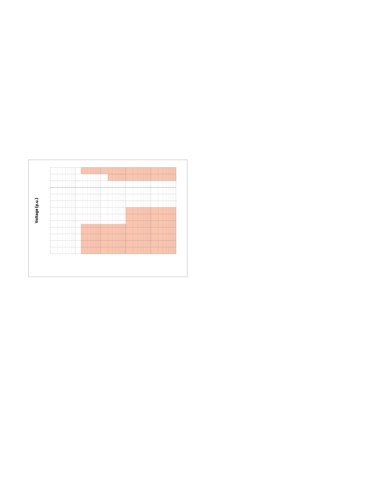
The trip zones may be used to describe a test mask. An
failure. Limits may be defined for low-voltage and high-
example of this is shown in Figure 2.
voltage ride-through measurements. In the case of a test
failure, the magnitude of the voltage and the time of the
1.30
1.20
failure can be recorded.
TRIP
1.10
1.00
In addition to defining the pass/fail mask, the oscilloscope
0.90
must be configured to acquire measurement data.
0.80
This includes:
0.70
0.60
• Vertical Scale set according to the nominal inverter
0.50
output voltage with sufficient headroom
0.40
0.30
TRIP
• Horizontal Scale set to acquire sufficient time per the
0.20
standards, with good time resolution
0.10
• Triggering configured to capture the undervoltage or
1.00
0.01
0.1
1
10
100
1000
overvoltage event.
Time (s)
(cumulative time for ride-through and clearing time for trip)
The ride-through measurements in the power analysis
software include a Power Preset button in the
Figure 2. Standards for smart inverters define ride-through limits for low-
voltage and high-voltage events.
measurement configuration that helps configure the
oscilloscope for optimal trigger, vertical, and horizontal
Standards for distributed energy resources define ride-
settings. This is further explained in the example
through and trip parameters for both undervoltage and
measurements below.
overvoltage events.
As the X-axis in Figure 2 shows, the timescales involved
The IEEE 1547.1 standard outlines three categories of
in this testing are relatively long-on the order of seconds
ride-through testing for Distributed Energy Resources
or even tens of seconds. Thus, the timebase settings are
(DERs), such as PV, ESS and other grid-tied inverters. Each
relatively slow, but oversampling is used to provide good
category represents an increasing level of grid support
measurement resolution.
capability and ride-through performance:
For LVRT, the preset configures a runt trigger where the
• Category I supports basic ride-through capability. The
peak voltage for a cycle fails to reach normal peak voltage.
testing ensures the DER does not trip immediately
For HVRT the trigger is set to edge trigger at greater than
during minor voltage disturbances. This is suitable
the normal peak voltage.
for areas where grid stability is less sensitive to
Once the oscilloscope has been preset, clicking the Go
DER behavior.
button arms the scope for a single sequence acquisition.
• Category II covers ride-through during deeper and
longer voltage excursions. The testing includes reactive
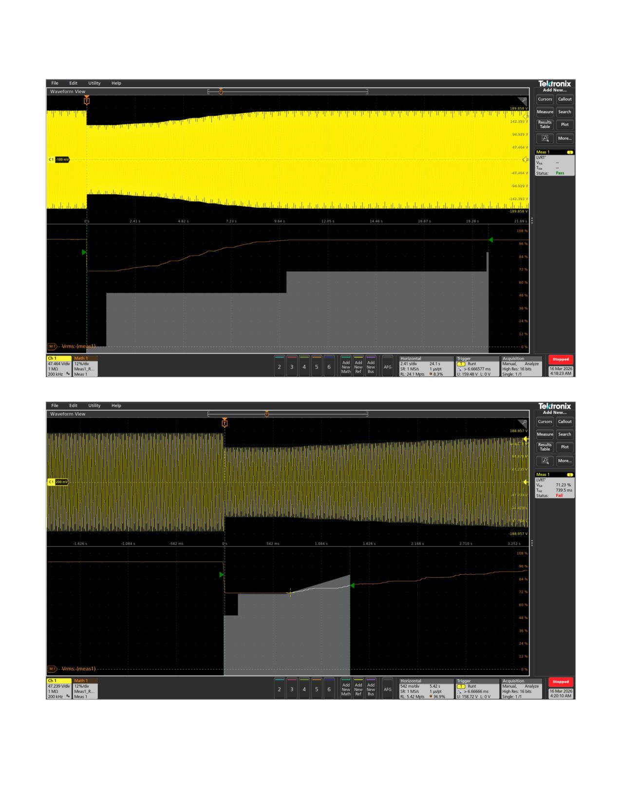
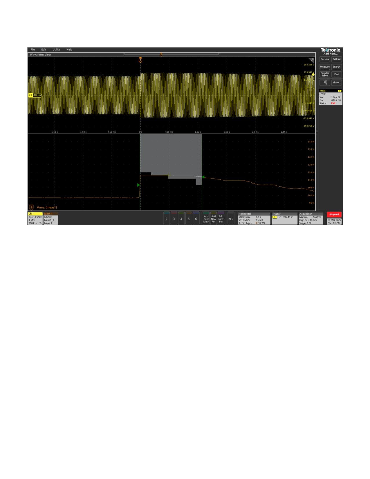
Figures 3 through 5 show examples of low-voltage and
power injection/absorption during faults. This is
high-voltage test results.
common in suburban or semi-urban grids.
4 | WWW.TEK.COM
Confirming Ride-through Conformance for Grid-tied Inverters with
Automated Oscilloscope Measurements
APPLICATION NOTE
Figure 3. This figure shows a pass condition for a low voltage ride-through test. The RMS voltage does not pass through the mask.
Figure 4. A low voltage ride-through failure. Vhit is the percentage of nominal voltage at which the mask has been hit. In this case the RMS voltage hit the mask at
71.23% of nominal. Thit is the time, relative to the start of the sag, at which the hit occurred. In this case the hit occurred 739.5 ms after the sag began..
WWW.TEK.COM | 5
Confirming Ride-through Conformance for Grid-tied Inverters with
Automated Oscilloscope Measurements
APPLICATION NOTE
Figure 5. A high voltage ride-through failure, in which the RMS voltage impinges on the mask.
6 | WWW.TEK.COM
Confirming Ride-through Conformance for Grid-tied Inverters with
Automated Oscilloscope Measurements
APPLICATION NOTE
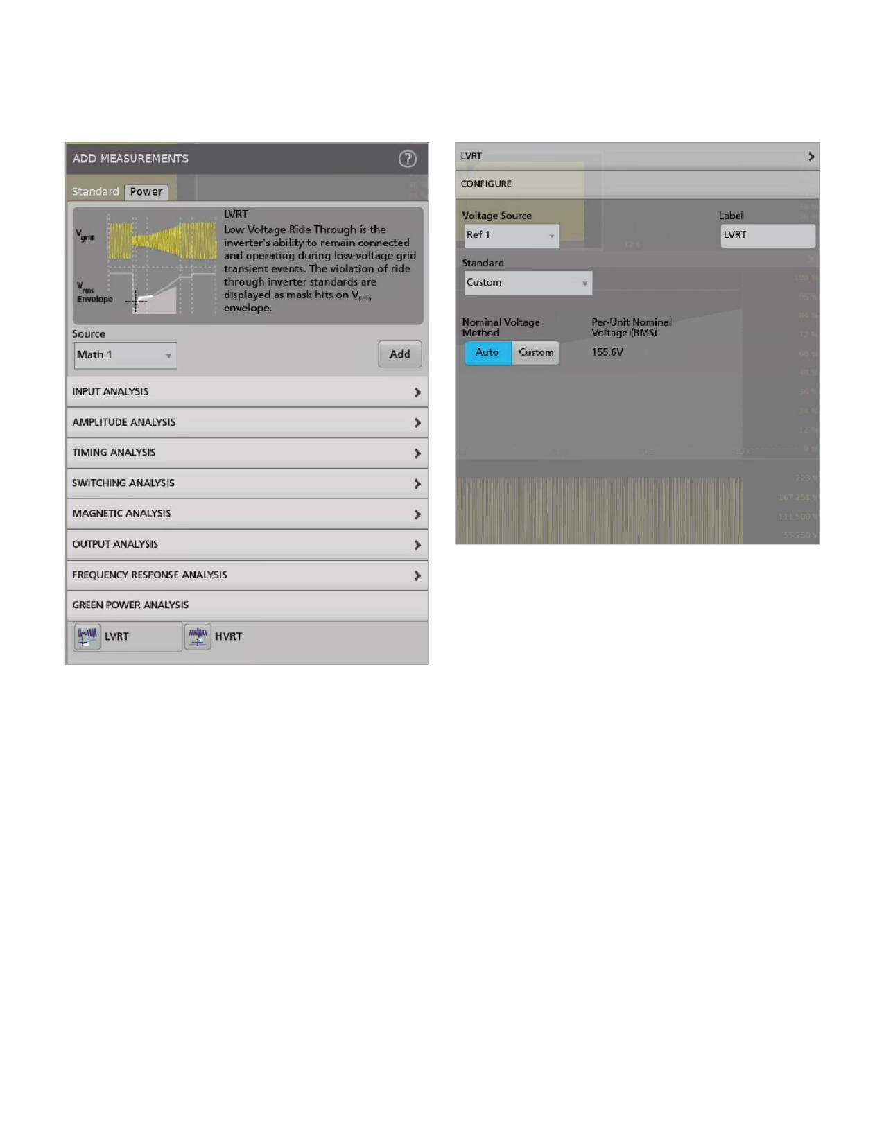
Setting up and executing a low voltage ride-through measurement
Figure 7. Settings for the Low Voltage Ride-through measurement.
Configuration of the measurement is straightforward
and is an important first step. The Configuration panel is
shown in Figure 7. It is also important to understand the
role of the Power Preset and Go buttons shown in Figure 9.
To understand the measurement process, we can work
Figure 6. Main menu for Advanced Power Measurement and Analysis suite.
through an example. In preparation for the measurement:
The LVRT and HVRT measurements are included in the
1.
The voltage source channel must be specified.
Advanced Power Measurement and Analysis suite available
2. The test standard to be used to generate the pass/fail
on 4, 5 and 6 Series B MSOs. These measurements are listed
mask must be specified. The measurement software
under the Power tab within the Add Measurements control.
includes mask settings for several different standards.
Since each standard includes timing requirements, the
oscilloscope uses this information to set the horizontal
scale during a Preset.
WWW.TEK.COM | 7
Confirming Ride-through Conformance for Grid-tied Inverters with
Automated Oscilloscope Measurements
APPLICATION NOTE
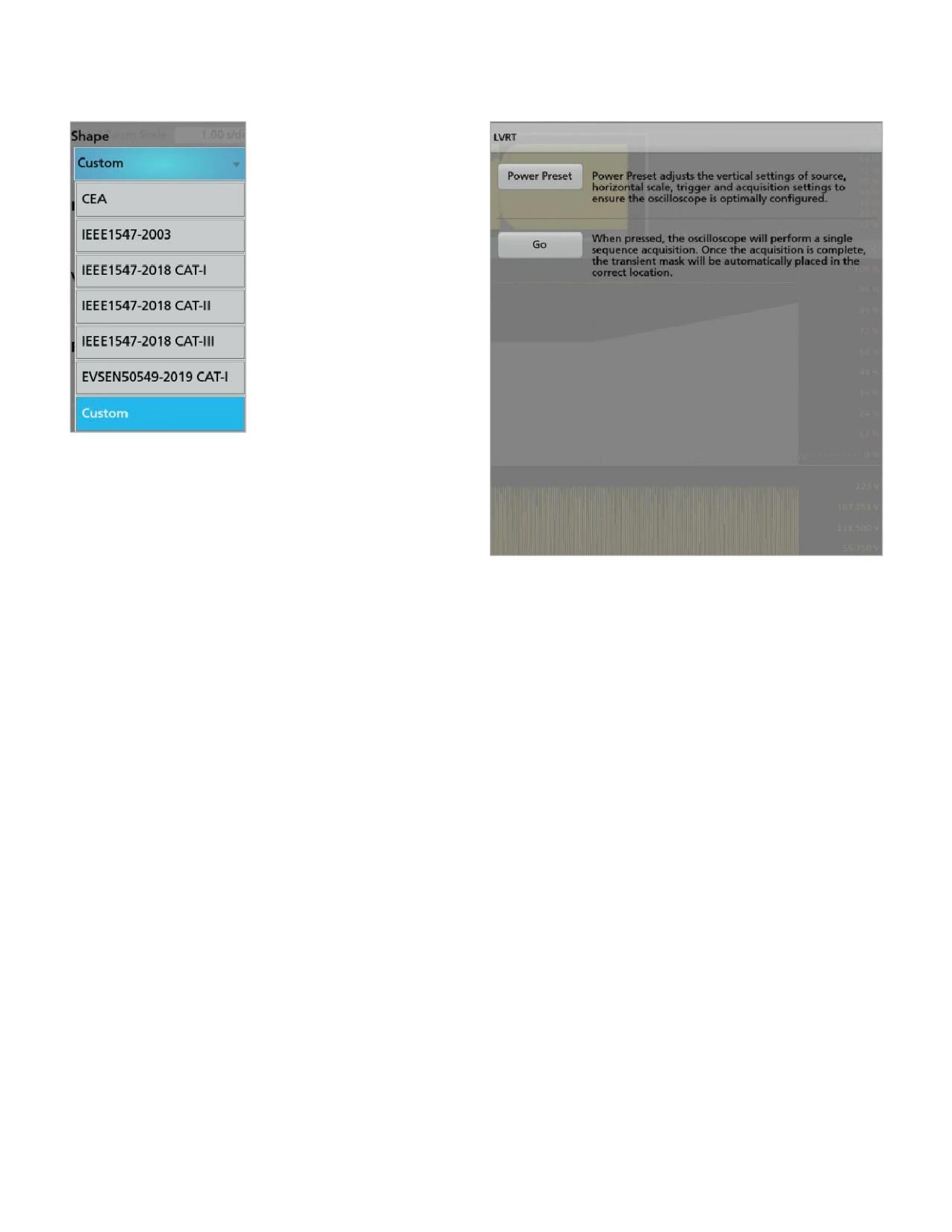
Figure 8. These standards are supported in ride-through measurements. One
can also define a custom mask for margin testing or to support proprietary
standards.
3. The nominal voltage can be automatically measured
by the oscilloscope or specified manually (Custom).
When the Nominal Voltage Method in the measurement
Figure 9. The default panel for the ride-through measurements. Power Preset
configuration is set to Auto, the Power Preset function
sets the vertical scale, horizontal scale and trigger. Clicking the Go button sets
captures eight cycles of the inverter’s continuous output
the scope for single shot and it waits for a trigger.
waveform and uses them to automatically adjust the
vertical and trigger settings. When the Nominal Voltage
Conclusion
Method is set to Custom, the system does not capture
the waveform; instead, it applies the vertical and trigger
Standards designed to ensure cooperation between grid-
settings directly, based on the user-defined per-unit
tied inverters and the power grid, specify ride-through
nominal voltage.
requirements for voltage events. Special power analysis
software is available to enable oscilloscope-based tests.
4. After configuration, one is ready to perform a Power
This can be an invaluable tool for designers working to
Preset (Figure 9). This prepares the oscilloscope based
prepare for conformance testing or debugging failures.
on the settings in the previous steps. Upon completion
of the Preset operation, if there are no errors on the
oscilloscope screen, the oscilloscope transitions to
References
Ready mode.
IEEE Standard for Interconnection and Interoperability of
5. Tapping the Go button from the measurement
Distributed Energy Resources with Associated Electric Power
configuration arms the oscilloscope for a Single
Systems Interfaces (IEEE Std 1547™-2018)
Sequence. To repeat the measurement using the
EVS-EN505049-1:2019+A1:2023; Requirements for generating
identical Power Preset configuration, tap the Go button
plants to be connected in parallel with distribution networks
again. Example test results are shown in Figures 3
- Part 1: Connection to a LV distribution network - Generating
through 5.
plants up to and including Type B
inverters-and-grid-services-basics
8 | WWW.TEK.COM

Contact Information:
Australia 1 800 709 465
Austria* 00800 2255 4835
Balkans, Israel, South Africa and other ISE Countries +41 52 675 3777
Belgium* 00800 2255 4835
Brazil +55 (11) 3530-8901
Canada 1 800 833 9200
Central East Europe / Baltics +41 52 675 3777
Central Europe / Greece +41 52 675 3777
Denmark +45 80 88 1401
Finland +41 52 675 3777
France* 00800 2255 4835
Germany* 00800 2255 4835
Hong Kong 400 820 5835
India 000 800 650 1835
Indonesia 007 803 601 5249
Italy 00800 2255 4835
Japan 81 (3) 6714 3086
Luxembourg +41 52 675 3777
Malaysia 1 800 22 55835
Mexico, Central/South America and Caribbean 52 (55) 88 69 35 25
Middle East, Asia, and North Africa +41 52 675 3777
The Netherlands* 00800 2255 4835
New Zealand 0800 800 238
Norway 800 16098
People’s Republic of China 400 820 5835
Philippines 1 800 1601 0077
Poland +41 52 675 3777
Portugal 80 08 12370
Republic of Korea +82 2 565 1455
Russia / CIS +7 (495) 6647564
Singapore 800 6011 473
South Africa +41 52 675 3777
Spain* 00800 2255 4835
Sweden* 00800 2255 4835
Switzerland* 00800 2255 4835
Taiwan 886 (2) 2656 6688
Thailand 1 800 011 931
United Kingdom / Ireland* 00800 2255 4835
USA 1 800 833 9200
Vietnam 12060128
* European toll-free number. If not
accessible, call: +41 52 675 3777
Rev. 02.2022
Find more valuable resources at TEK.COM
Copyright © Tektronix. All rights reserved. Tektronix products are covered by U.S. and foreign patents, issued and pending. Information in this publication supersedes that
in all previously published material. Specification and price change privileges reserved. TEKTRONIX and TEK are registered trademarks of Tektronix, Inc. All other trade names
referenced are the service marks, trademarks or registered trademarks of their respective companies.
040726 SBG 48W-74236-0