At a battery conference several months ago, I demonstrated how a source measure unit (SMU) can measure the internal resistance of energy storage devices such as a battery or a fuel cell by changing the load current from the battery operating current (commonly called the polarizing current) to the open circuit potential, and simultaneously measuring the change in cell voltage throughout the event. In this “current interrupt method” of measuring the internal resistance of an electrochemical cell, the battery’s internal resistance is equal to the change in voltage divided by the change in current.
The demonstration was a big hit because it showed how the battery internal resistance could be measured at large polarization currents, something that a frequency response analyzer (FRA) or electrochemical impedance analyzer (EIS) instrument cannot accomplish. Historically, electrochemists have implemented this method using an oscilloscope and a switch (for the load), and have achieved what I would call a figure of merit, rather than the real internal resistance. The point is, there are many nonobvious details that need to be considered in order to get the correct internal resistance using this method.
Let’s discuss how I was able to get my internal resistance measurements, using this interrupt method, to match the internal resistance measurements measured from an expensive FRA or EIS instrument.
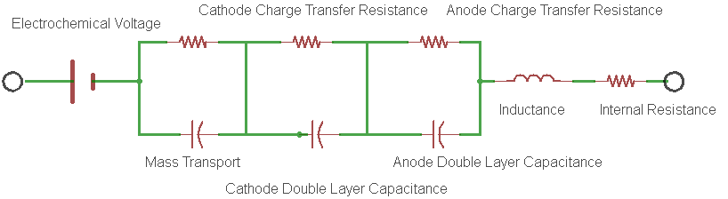
The battery internal resistance is a measurement of the real part of the complex impedance of the cell. Figure 1 shows the simplest electrical model of this complex impedance and is known to most electrochemists as the Randles circuit model.

Figure 1: An example of a Randles Circuit Model equivalent circuit.
In the model, each electrode redox reaction is modeled with a resistor and a capacitor representing the charge transfer resistance and the double layer capacitance for the electrode respectively.
- The charge transfer resistance represents the activation energy required to drive the intended electrode reaction forward at a specific rate.
- The double layer capacitance is a measure of the slowness of the electrode reaction resulting from charges building up on each side of the electrode, again at that same specific rate.
- Rint is the real component of the impedance of the cell.
For most cells, it is the supporting electrolyte (being an ionic conductor), that ends up dominating the magnitude of this resistance. Electronic conduction of the electrodes and external interconnection resistances are usually much smaller contributors to the total battery internal resistance. The passage of current through this real resistance will generate heat, which is a very important condition to consider. Many failure mechanisms of the cell show themselves through elevated measurements of the internal resistance. The characteristics of the internal resistance are generally very useful in determining the overall health of an electrochemical cell.
So just how does the current interrupt method measure the real part of the complex impedance? Well, it’s easy to see by referring to the Randles circuit model in Figure 1. In the model, the geometrical inductance of the cell and the test instrumentation interconnects is shown along with the electrode parameters that we discussed earlier. Note that if this measurement is set-up without remote sensing enabled, the inductance shown in the model will be the total inductance of the measurement loop shown in Figure 2A below. With remote sensing enabled, only the inductance of the cell itself will be measured (Figure 2B). Here we are only measuring the impedance between the sensing leads, complex or not. In order to measure Rint, we need to interrupt or change the cell current for just the right amount of time so that the reactance’s sum to zero, thereby leaving only the measurement of the real part of the internal resistance (Figure 2D). In general, there will be only one interrupt delay that will satisfy this requirement for any given cell and measurement geometry. I would expect interrupt intervals to vary from 80 microseconds to several milliseconds depending on the size and configuration of the cell.

Figure 2: Measuring cell internal resistance
In order to properly measure the internal resistance of an electrochemical cell, it is common to run an EIS plot, or to measure the complex impedance of the cell over the operating range of cell currents. The internal resistance will be the point on the curve where the complex impedance crosses the real axis, or when the reactive components sum to zero. A plot of the complex impedance is shown below for reference. The current interrupt method of measuring Rint will impart a scalar measurement, representing the magnitude of the impedance vectors shown superimposed on the complex impedance plot shown in Figure 3. The correct interrupt time can be easily found by varying the interrupt delay to minimize the vector magnitude, shown as Rint in Figure 3. The other vectors, R1 and R2, obtained by changing the interrupt interval, will show larger magnitudes. You should also notice that the second x axis crossing is not the battery internal resistance but rather the sum of all resistances in the model from Figure 1. This point is shown as Rt in Figure 3.

Figure 3: Example complex impedance chart
So there you have it, a short concise method for obtaining the correct internal resistance for batteries and electrochemical cells using the current interrupt method. Depending on the measurement need, a variety of instruments from Keithley can be used as an electrochemical instrument capable of operating as a galvanostat or a potentiostat. Many of these instruments are fast enough to accomplish this measurement. Keithley source measure units (SMU’s) are able to measure the internal resistance of batteries, fuel cells, or any electrochemical cell while providing the polarization current. The Keithley 2651A SMU is particularly interesting because a single 2651A is capable of delivering a 50A step change in load current to up to 10V of cells at once!
James Niemann has been an analog design engineer at Keithley Instruments in Cleveland from 1988 to the present. He is currently a principle design engineer responsible for general R&D as well as the design of new products. James Niemann has been an analog design engineer at Keithley Instruments in Cleveland from 1988 to the present. He is currently a principle design engineer responsible for general R&D as well as the design of new products used for electrochemical research.