We’re in a new age of data. As our world becomes more enabled and new technologies are implemented, the world is experiencing an explosion in the amount of data being generated and processed. According to Statista global research, there will be 97 Zettabytes of data created this year. Even more jarring is the acceleration of the pace at which that data is being created; a 2020 study delivered by LinkedIn found that 90 percent of the data in the world at the time was created over the preceding 2 years.
DDR5 Test Challenges
Consumers’ increased appetite for technology and the ensuing deluge of data that needs to be stored, processed, and transmitted creates a need for a faster DRAM, hence the importance of fifth generation DRAM (DDR5). DDR5 not only improves bandwidth and channel efficiency, but it also supports tremendous amount of density. DDR5 supports maximum memory density of 64Gb per die. This represents almost 4x increase compared to DDR4. Previous generations of DDR DRAM have typically doubled their memory capacity over predecessors.
Higher data transfer rates and higher density DRAM with increasingly smaller form factor lead to complex designs that push the boundaries of signal integrity and require higher performance hardware/software for accurate DRAM compliance, debugging and validation. LPDDR5 & DDR5 DRAM testing brings many formidable challenges, including signal access, de-embedding, and Rx equalization. This blog provides a primer on the challenge of signal access.
Interposer Use Increases
There are three main HW topologies that a user should be aware of for LPDDR and DDR SDRAM validation:
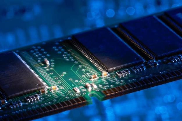
- DIMM Based Setup – This is a typical setup used in server and desktop applications. DIMMs are memory sticks or a module that contains one or several DRAMs soldered to it. Most common configuration is a dual-rank DIMM. In case of dual rank, DRAMs are soldered on both sides of the DIMM. The only way to probe the memory interface is to solder an interposer beneath the DRAM. (Figure 1)

Figure 1: DDR Dual Rank Setup
- Direct Solder Setup - This is a setup most used in embedded applications like laptops, Industrial IoT and automotive. In this case, a DRAM is soldered directly on the motherboard (Figure 2). As speeds increase and signal integrity becomes critical, there might not be thru-vias available on the backside of the motherboard to access the signals. This means the only other means to access the DDR bus is to use an interposer underneath the DRAM.
Figure 2: Direct-Attach Configuration
- Package-on-package (POP) setup – This is a common setup for LPDDR DRAMs. It is highly used in Mobile and consumer IoT applications. In this format, DRAM is placed right on top of the CPU (Figure 3). Again, the only way to gain signal access in this setup would be to insert an interposer in between SOC and the LPDDR DRAM.
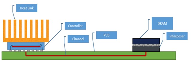
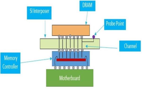
Figure 3: LPDDR5 POP Setup
Faster, Smaller, Sleeker
In response, Tektronix has developed the Flex Long Reach (FLR) probe tips (Figure 4). This tip is the culmination of significant collaboration with memory validation engineers to understand and address their test probing problems. The FLR tips provide superior slim form-factor and improved reach for enabling access to increasingly difficult signal sources. In addition, they offer enhanced strain relief resulting from the use of a flexible PCB substrate that accommodates a variety of testing needs together with the convenience of the loaded loss parameters, which provides automatic de-embedding to account for the probe and interposer loss.
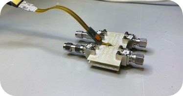
Figure 4: P77STFLRB Tip
Collaborating to Streamline DDR Interposer Workflows
With the adoption of newer standards and their corresponding higher data rates, the number of cases/workflows requiring interposers will only increase. This has led Tektronix to work with Nexus to fine-tune the ability of our probe tips to work with their interposers. (Contact Tektronix for information on compatibility with other off-the-shelf interposers.)
For users, this directly results in better signal access, improved strain relief, superior signal fidelity, and greater accuracy of their measurements.
Our Flex Long Reach tips (P77STFLRB and P77HTFLRB) provide an out-of-box solution when used with nexus XH interposers. An embedded 55-Ohm resistor, de-embedding parameters, as well as a nominal interposer model are loaded onto the oscilloscope and activated upon tip attachment. Upon connection to the scope, the P7700 series probes automatically identify the accessory connected to the probe and a unique DSP filter providing a calibrated response is enabled. These unique filters also de-embed probe parasitics (See Figure 2: DDR Dual Rank Setup) from the measurement. Creating probe and tip specific filters is critical as bandwidths increase. At high bandwidth, small variations in the signal path can lead to significant variation in frequency response which cannot be corrected using a normal DSP filter.
Our Flex Long Reach tips also exclusively feature our Lightfoot accessories (Figures 5 & 6). These plastic clips can be glued down or taped down to the DUT (Device Under Test), allowing the probe tips to be snapped in place for a secure hold during the entirety of the test.
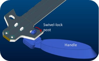
Figure 5: Lightfoot Probe Accessory
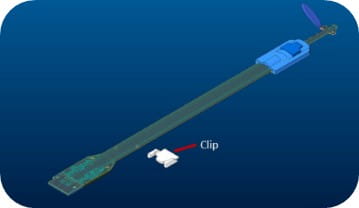
Figure 6: Lightfoot Probe Clip