联系我们
与泰克代表实时聊天。 工作时间:上午 9:00 - 下午 5:00(太平洋标准时间)。
致电我们
工作时间:上午9:00-下午5:00(太平洋标准时间)
下载
下载手册、产品技术资料、软件等:
反馈
Automotive Ethernet Test Application
Multigigabit Ethernet (Opt. AUTOEN10G), 1000/100BASE-T1 (Opt. BRR), 10BASE-T1S (Opt. AUTON10) Datasheet
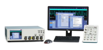
Tektronix options AUTOEN10G (MultiGBASE-T1), BRR (100BASE-T1/1000BASE-T1) and AUTOEN10 (10BASE-T1S) comprise the most comprehensive solution for Automotive Ethernet transmitter compliance testing, as well as debug and validation of Automotive Ethernet devices and ECU's, against the IEEE and Open Alliance specifications. The test suite runs on the MSO/DPO70000DX and DPO70000SX, letting you take full advantage of validation and debug capabilities in the oscilloscope, in addition to compliance testing. The integration of Automotive Ethernet is placing greater demands on technology and is placing even greater demands on comprehensive design validation to ensure interoperability between multiple ECU's and reliability in demanding environments. A complete testing solution enables passing strict compliance tests and provides greater confidence in design margins under real-world conditions.
The Tektronix Automotive Ethernet application allows you to select the reference specification, and the test plan depending on the selected specification and currently supports the following data rates and standards:
- 10BASE-T1S as per IEEE 802.3cg and OPEN Alliance TC14.
- 100BASE-T1 as per IEEE 802.3bw and OPEN Alliance TC1.
- 1000BASE-T1 as per IEEE 802.3bp and OPEN Alliance TC12.
- 2.5/5/10GBASE-T1 as per IEEE 802.3ch and OPEN Alliance TC15 1
Features and benefits
Test coverage:Tektronix Automotive Ethernet application covers transmitter compliance tests for 100BASE-T1 (IEEE 802.3bw), 1000BASE-T1 (IEEE 802.3bp), MultiGBASE-T1 (IEEE 802.3ch), and 10BASE-T1S (IEEE 802.3cg) standards through a single Automotive Ethernet compliance application. The application uses the TekExpress automation framework and tests as per IEEE and Open Alliance specification for Tektronix DPO70000 SX/DX and MSO's.
Test time: Fully automated with setup wizard, configures all required test parameters to perform compliance testing as per Automotive Ethernet standards. Highly optimized and intuitive user interface for quick test configuration and validation of electrical signals.
Accuracy:The application runs on Tektronix DPO70000 SX/DX series oscilloscopes for accurate and repeatable results.
Pattern matching: Verifies that the correct set of compliance patterns are sent by the transmitter before acquiring signals for compliance analysis.
Reporting: Compiles all test results into a customizable report with pass/fail results for easy analysis and record keeping, as well as margin testing.
Compliance and debug: Provides a toolkit of DPOJET based setups to quickly switch into debug and validation mode when a DUT fails compliance.
Analysis and debug tools: Supporting tools, such as TekExpress user defined Mode, advanced DPOJET jitter analysis (Opt. DJA), PAM4 Eye Diagram Analysis (Opt. PAM4) tools help to catch problems before compliance testing, or root-cause the problem in the event of a failure.
Performance verification: The Automotive Ethernet application allows you to run a test multiple times and save or stop acquisitions in the event of an out-of-limit condition. The report shows statistics with pass/fail results for each run to show device performance over multiple runs.
PHY level protocol decode: Opt. SR-AUTOETH1 decodes and displays 100BASE-T1 data in a protocol-aware view. A time-correlated event table view with waveforms allow you to quickly search through decoded data for events of interest.
Comprehensive programmatic interface: Enables automation programs and scripts to call Automotive Ethernet test functions.
Automated Automotive Ethernet compliance application
Physical layer compliance tests have been defined to ensure the interoperability between different designs and hardware vendors. Tektronix Automotive Ethernet compliance testing application provides the most comprehensive solution to serve the need of engineers designing Automotive Ethernet silicon or electronic control units (ECU's), as well as those validating physical layer compliance of Automotive Ethernet as per IEEE or Open Alliance specifications.
| 10BASE-T1S | 100BASE-T1 | 1000BASE-T1S | MultiGBASE-T1 | |
|---|---|---|---|---|
| IEEE Specification | 802.3cg | 802.3bw | 802.3bp | 802.3ch |
| Data rate | 10 Mbps | 100 Mbps | 1 Gbps | 2.5/5/10 Gbps |
| Symbol rate | 12.5 MHz | 66.66 MHz | 750 MHz | 1.4/2.8/5.6 GHz |
| Line coding | 4B/5B, DME | PAM3 | PAM3 | PAM4 |
| Voltage | 1 Vpp | 2.2 Vpp | 1.3 Vpp | 1.3 Vpp |
| Communication | Half Duplex | Full Duplex | Full Duplex | Full Duplex |
Industry defined testing for Automotive Ethernet
The IEEE and Open Alliance provide compliance tests for an Automotive Ethernet PHY or ECU. As per the IEEE and Open Alliance, we have the following compliance requirements for Physical Media Attachment (PMA) transmitter test for an Automotive Ethernet PHY or ECU.
| Test name | 100BASET1 IEEE 802.3 bw | ECU TC8 100/1000B ASE-T1 | 1000BASE -T1 IEEE 802.3 bp | MultiGBA SE-T1 IEEE 802.3 ch |
Transmitter output Droop | 96.5.4.1 | OABR_PM A_TX_01 | 97.5.3.1 | 149.5.2.1 |
Transmitter Distortion | 96.5.4.2 | OABR_PM A_TX_08 | 97.5.3.2 | NA |
Transmitter Linearity | NA | NA | NA | 149.5.2.2 |
Transmitter Timing Jitter in Master/Slave Mode | 96.5.4.3 | OABR_PM A_TX_02 | 97.5.3.3 | 149.5.2.3 |
Transmitter MDI Jitter | NA | NA | 97.5.3.3 | NA |
Tx MDI Random Jitter (Master) | NA | NA | NA | 149.5.2.3.1 |
Tx MDI Deterministic Jitter (Master) | NA | NA | NA | 149.5.2.3.2 |
Transmitter Power Spectral Density (PSD) | 96.5.4.4 | OABR_PM A_TX_04 | 97.5.3.4 | 149.5.2.4 |
Transmit Clock Frequency | 96.5.6 | OABR_PM A_TX_03 | 97.5.3.6 | 149.5.2.6 |
Transmitter Peak Differential Output | 96.5.4.5 | NA | 97.5.3.5 | 149.5.2.5 |
| MDI Return Loss | 96.8.2.1 | OABR_PM A_TX_05 | 97.7.2.1 | 149.8.2.1 |
MDI Mode Conversion | NA | OABR_PM A_TX_06 | NA | NA |
Common Mode Emission | NA | Only 100BASET1 | NA | NA |
Each test requires the engineer to set the required test mode, acquire waveforms with the correct instrument settings, and analyze the results per the standard. Manually capturing and analyzing them is tedious, time consuming, and subject to errors.
The TekExpress Automotive Ethernet compliance application allows you to automatically execute physical layer electrical tests for transmitter compliance using IEEE and/or Open Alliance (OABR) specifications. The Tektronix Opt. BRR and AUTOEN10G applications combine to form a TekExpressTM compliance automation solution for 100BASE-T1, 1000BASE-T1 and MultiGBASE-T1 Automotive Ethernet with a single user interface. The TekExpress Automotive Ethernet application is configured by following a step-bystep process. The application sets up the oscilloscope and automates testing, guiding you to accurate and repeatable results.
MultiGBASE-T1 PMA transmitter compliance measurements
MultiGBASE-T1 is specified in IEEE 802.3ch, an extension to BASE-T1 PHYs at speeds in excess of 1000 Mb/s, including 2.5GBASE-T1, 5GBASE-T1, and 10GBASE-T1. The physical layer operates over a single pair of shielded cable in full-duplex mode with four level pulse amplitude modulation (PAM4).
| Test specification | Test mode | Pattern type | Instrument |
|---|---|---|---|
| Tx Output Droop | 6 | Oscilloscope | |
| Tx Linearity | 4 | PAM4 | Oscilloscope |
| Tx Timing Jitter (Master and Slave) | 1 | Clock | Oscilloscope |
| Tx MDI Random Jitter (Master Mode) | 2 | Square | Oscilloscope |
| Tx MDI Deterministic Jitter (Master Mode) | 2 | JP03A | Oscilloscope |
| Even Odd Jitter (EOJ) | 2 | JP03B | Oscilloscope |
| Tx Power Spectral Density and Power level | 5 | PAM4 | Oscilloscope |
| Tx Clock Frequency | 1 | Clock | Oscilloscope |
| Tx Peak Differential Output | 5 | PAM4 | Oscilloscope |
| MDI Return Loss | Slave | VNA |
| Test specification | Test mode | Pattern type | Instrument |
|---|---|---|---|
| Tx Output Droop | 6 | Oscilloscope | |
| Tx Distortion | 4 | PAM3 | Oscilloscope |
| Tx Timing Jitter (Master and Slave) | 1 | Clock | Oscilloscope |
| Tx MDI Jitter | 2 | Clock | Oscilloscope |
| Tx Power Spectral Density and Power level | 5 | PAM3 | Oscilloscope |
| Tx Clock Frequency | 1 | Clock | Oscilloscope |
| Tx Peak Differential Output | 5 | PAM3 | Oscilloscope |
| MDI Return Loss | Slave | Vector Network Analyzer or Oscilloscope + AWG | |
| MDI Mode Conversion | Slave | VNA |
| Test specification | Test mode | Pattern type | Instrument |
|---|---|---|---|
| Tx Output Droop | 6 | Oscilloscope | |
| Tx Distortion | 4 | PAM4 | Oscilloscope |
| Tx Timing Jitter (Master and Slave) | 1 | Clock | Oscilloscope |
| Tx Power Spectral Density and Power level | 5 | PAM3 | Oscilloscope |
| Tx Clock Frequency | 2 | Clock | Oscilloscope |
| Tx Peak Differential Output | 5 | PAM3 | Oscilloscope |
| MDI Return Loss | Slave | VNA | |
| MDI Mode Conversion | Slave | VNA | |
| MDI Common Mode Emission | 5 | PAM3 | Oscilloscope |
| Test specification | Test mode | Instrument |
|---|---|---|
| Tx Output Droop | 2 | Oscilloscope |
| Tx Timing Jitter | 1 | Oscilloscope |
| Tx Power Spectral Density and Power level | 3 | Oscilloscope |
| Tx Peak Differential Output | 1 | Oscilloscope |
| MDI Return Loss | Slave | Oscilloscope + AFG |
The TekExpress Automotive Ethernet automated testing application
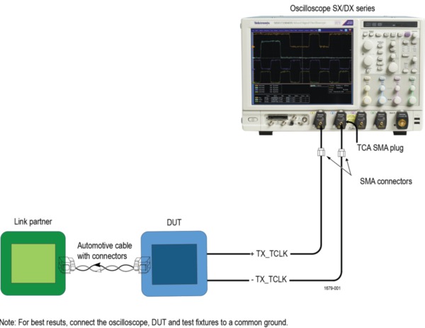
The Tektronix Automotive Ethernet application offers exceptional ease of use with the TekExpress Automation platform. Testing follows a logical workflow for quick, easy test setups, changes and review of test results. Valid testing requires proper cabling, probes, and connections between fixtures, instruments, and the device under test (DUT). The TekExpress Automotive Ethernet application provides setup instructions for each test, with images and reference illustrations showing correct configurations. It generates a comprehensive, date-stamped test report with pass/fail results, waveforms, and data plots.
Accurate, repeatable compliance tests follow a 5-step workflow.
Step 1: Selection of test suite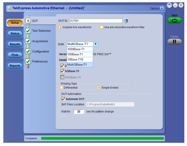
Test selections includes Automotive Ethernet 100BASE-T1, 1000BASE-T1, and MultiGBASE-T1. You can select different speed gears for MultiGBASE-T1. The test selection, test limits, and configuration will be selected based on the test suite chosen. You can test using live oscilloscope waveforms or previously recorded waveforms or sessions.
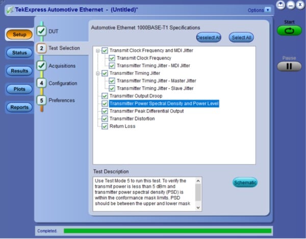
Step 2: Test selection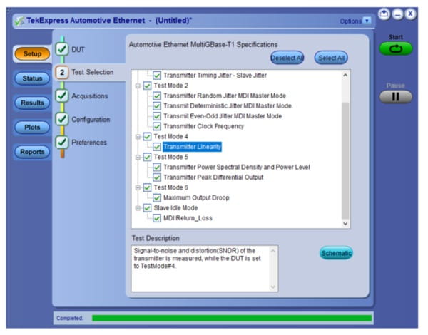
Based on the test suite selection in Step 1, the TekExpress Automotive Ethernet application allows you to select one or multiple tests from the test tree for the respective test suite.
A schematic views and descriptions guide you through connections, along with test information and golden waveforms. If you select multiple tests, the application will provide prompts to set the correct DUT test mode and make the appropriate connections.
Step 3: Signal validation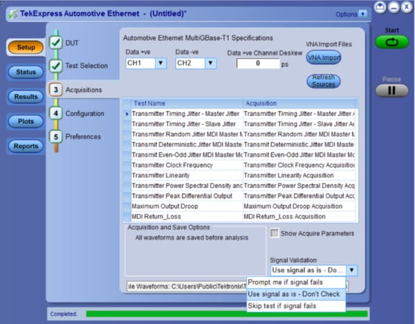
It is important to validate the signal parameters before performing a compliance test. The TekExpress application checks for the correct test mode waveform before running any test. This ensures that the proper test connections are in place and that the DUT is sending the appropriate test pattern.
Step 4: Configuration of User defined and Compliance Mode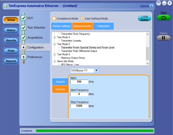
The TekExpress Automotive Ethernet application allows you to configure the test in compliance mode or user defined mode. In compliance mode, the application configures the oscilloscope per the test procedure defined in the test specifications from the applicable standard. The DUT is tested against limits defined by the standard.
In user defined mode, you can change the test parameters such as record length, sample rate, etc., as well as test limits. User-defined Mode allows you to test your device beyond compliance.
Step 5: Preferences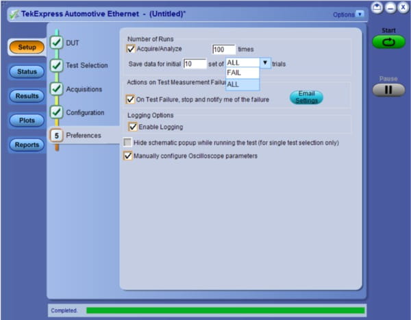
The TekExpress application allows you to run multiple consecutive tests for statistical analysis. You can save the waveforms from failed tests for debugging.
Pass/Fail report: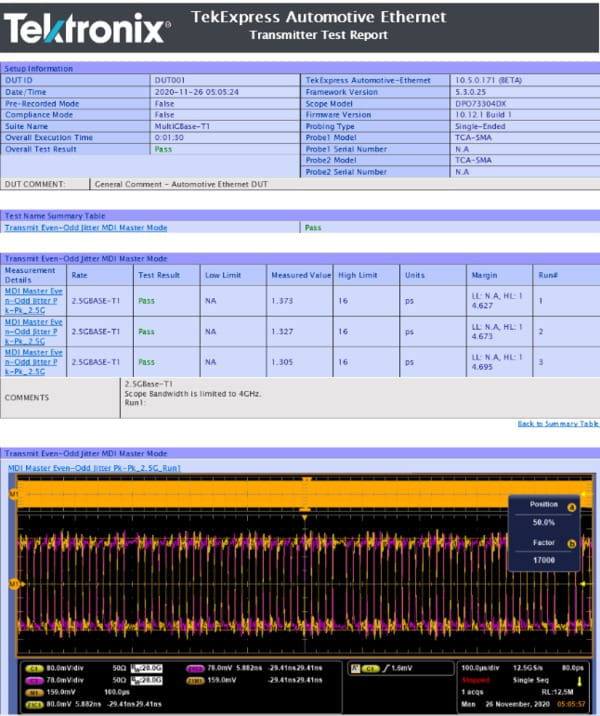
Creating compliance test documentation is quick and easy in the TekExpress application with a summary report in MHL or PDF formats. The TekExpress application generates a report after the test execution is complete, and includes pass/fail status to quickly analyze the test results. The report also includes test configuration details, waveform plots, oscilloscope displays, margin analysis, and statistical analysis to provide insights into your design.
Single instrument for time domain and frequency domain measurements
Automotive Ethernet compliance testing includes time domain measurements like jitter, droop, clock frequency and peak differential output. It also includes frequency domain measurements such as power spectral density and return loss. The Tektronix Automotive Ethernet application allows you to perform all of these measurements using an oscilloscope, eliminating the need to connect a spectrum analyzer or vector network analyzer.
Return loss measurement
The MDI return loss measurement determines the impedance mismatch from the differential impedance specification of 100 Ω, which will affect hardware interoperability. Return loss is a frequency domain measurement, but the Automotive Ethernet application can perform this test with an oscilloscope and function generator using a patented measurement approach. Return loss using this method is available for 10BASE-T1S, 100BASE-T1, and 1000BASE-T1.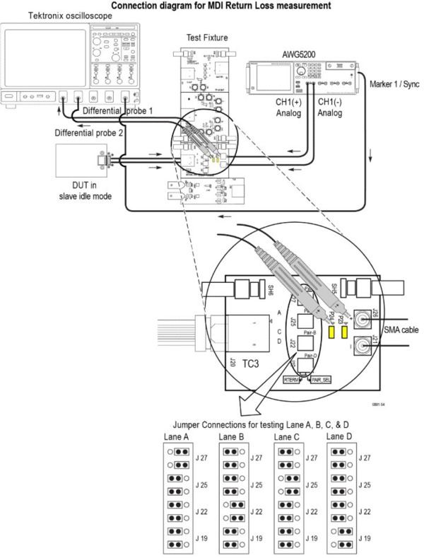

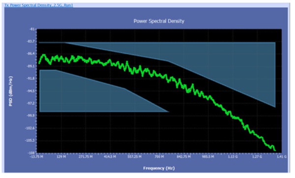
Power spectral density
The power spectral density of a test signal for the selected standard is computed using oscilloscope math functions. Post processing is done on the signal to arrive at the PSD. The computed PSD is then compared with the specification by using lower and upper masks to arrive at the final result.
Analysis and debug beyond compliance
If a DUT fails any portion of the compliance test, powerful debugging and analysis tools such as DPOJET jitter analysis, PAM4 analysis, and protocol decoding are available to determine root cause and examine system-level performance.
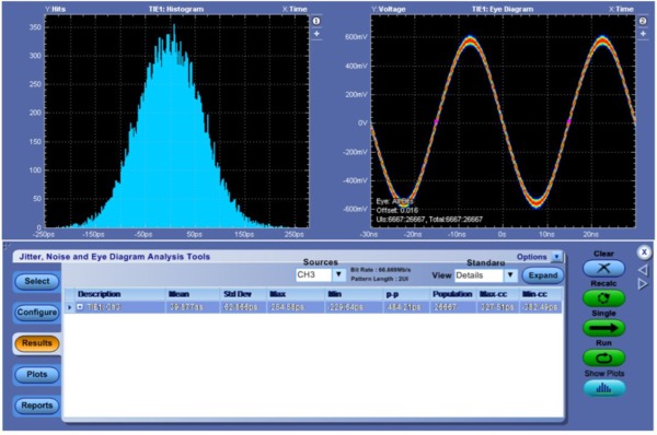
DPOJET Jitter Analysis measurements (Opt. DJA)
The new jitter measurements introduced with MultiGBASE-T1 Ethernet provide separate limits for Deterministic Jitter (DJ), Even Odd Jitter (EOJ) and Random jitter (Rj). The DPOJET jitter analysis tool provides additional analysis capabilities like crosstalk and power noise separation to help find the root cause of failures.
Jitter tests quantify the timing variations of the edges of the signal, using specified test patterns. These jitter measurements include the contributions from duty cycle distortion and baseline wander. Jitter is determined by accumulating waveforms and measuring the width of the accumulated points at the eye crossing. The peak-to-peak jitter is inferred from minimum and maximum values in the tails of the histogram. 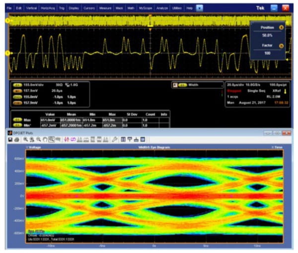
Apart from jitter measurements for MultiGBASE-T1, DPOJET allows you to perform analysis for following measurements:
- Clock frequency and transmitter amplitude with histogram and trend analysis
- Positive and negative droop measurements
- Full characterization of jitter performance including TIE and histogram profiles.
PAM4 Analysis (Option PAM4)
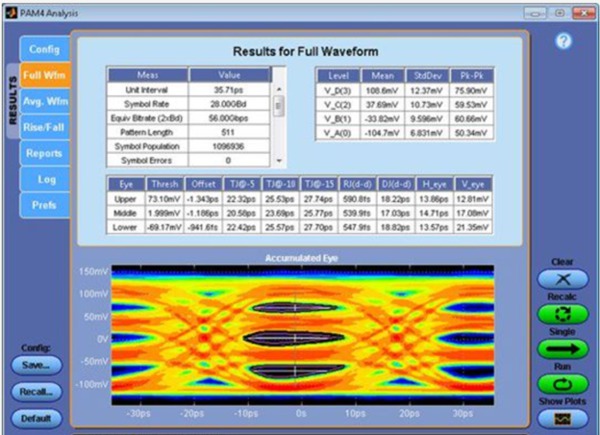
Automotive MultiGBASE-T1 uses four-level Pulse Amplitude Modulation (PAM4) for physical layer transmission since PAM4 signaling needs half the bandwidth as NRZ for the same data rate. However the 4 levels of PAM4 introduce additional complexity in signaling and place new demands on the test methodology. The PAM4 analysis tool offers several measurement and visualization capabilities to make validating PAM4 designs significantly more efficient.
PAM4 Analysis
- Enhanced software clock recovery offers the industry's most robust clock recovery capability even from heavily impaired signals.
- Integrated receiver equalization: Apply CTLE, FFE and DFE equalization to the acquired waveform to open a closed eye. Model different types of receiver settings to perform what-if analysis.
- Configurable Bessel-Thomson filter offers the flexibility to tune bandwidth of the measurement receiver, either manually or automatically, based on detected data rate.
- Waveform filter enables embed or de-embed test fixtures or channel models.
PAM4 Measurements
- Jitter measurement and eye analysis: Full Characterization of the PAM4 eyes to support standard based and debug analysis.
- Rise and fall times for all 12 PAM4 transitions offer the capability to analyze each transition type in the PAM4 signal.
- Symbol and bit error detector: Accumulate SER and BER over multiple acquisition cycles.
Plots and reports
- Comprehensive plots enable in-depth analysis: HTML report captures all the relevant setup configuration, measurement test results, and plot in single file that is easy to read and share. Measurement results across multiple acquisitions can be exported to a consolidated CSV file for easy multi-run analysis.
Automotive Ethernet decoder for 100BASE-T1 (Opt. SR-AUTOETH1)
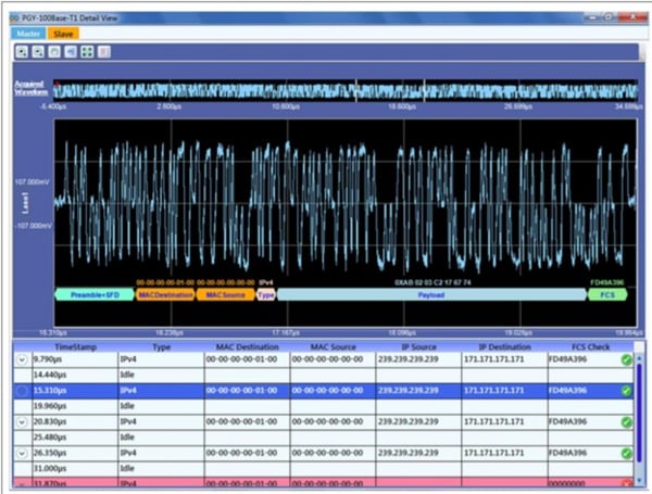
Decode and display Automotive Ethernet data in a protocol-aware view with the characters and names that are familiar from the standard such as the ordered sets: SOF, Electrical Idle, and EOF.
You can now feed the output of directional coupler to Tektronix oscilloscope for time domain view. SR-AUTOETH1 100BASE-T1 protocol decode software runs on DPO70000SX and MSO/DPO70000 Series oscilloscopes and easily decodes PAM3-encoded 100BASET1 signal. This enables engineers to quickly understand the protocol activity between the ECUs. A time-correlated event table view with waveform allows for quickly searching through events of interest simultaneously.
Key feautures
- Decodes PAM3 encoded 100BASE-T1 signals.
- Decodes Send_N mode packets without any training sequence.
- Validate FCS and reports error packets in red.
- Display the time stamp, packet type, IP source and destination address, decoding of the payload.
- Detail view correlates the decoded packets with waveform using a bus diagram.
- Separately displays Master and Slave packets.
- Export the decoded data in CSV or TXT file format.
- Report generation.
1Refer Ordering information section to know more about bandwidth requirements.
Ordering information
| Standard | Compliance test | Instrument | Model number |
|---|---|---|---|
| Multigigabit Ethernet | Droop, Linearity, Dj and Rj Jitter, Power Spectral Density, Clock frequency, Peak Differential output | Oscilloscope with bandwidth
| DPO70000 SX/DX series, MSO6B series |
| MDI Return Loss | Vector Network Analyzer with bandwidth ≥ 4 GHz | 8.5 GHz ShockLine MS46522B 2-port Anritsu VNA | |
| 1000BASE-T1 | Droop, Jitter, Power Spectral Density, Clock frequency, Peak Differential output | Oscilloscope with bandwidth ≥ 2 GHz | DPO70000 C/SX/DX series, MSO5/6B series |
| Distortion Test | 2 channel Function Generators with bandwidth ≥ 125 MHz | AFG31000 series or AWG5200 | |
| MDI Return Loss | AWG or Vector Network Analyzer | 8.5 GHz ShockLine MS46522B 2-port Anritsu VNA | |
| MDI Mode conversion | Vector Network Analyzer | 8.5 GHz ShockLine MS46522B 2-port Anritsu VNA | |
| 100BASE-T1 | Droop, Jitter, Power Spectral Density, Clock frequency, Peak Differential output, Common mode emission | Oscilloscope with bandwidth ≥ 1 GHz | DPO70000 C/SX/DX series, MSO5/6B series |
| Distortion Test | 2 channel Function Generators with bandwidth ≥ 25 MHz | AFG31000 series | |
| MDI Return loss | AFG(125 MHz) or Vector Network Analyzer | 8.5 GHz ShockLine MS46522B 2-port Anritsu VNA | |
| MDI Mode conversion | Vector Network Analyzer | 8.5 GHz ShockLine MS46522B 2-port Anritsu VNA | |
| 10BASE-T1S | Droop, Jitter, Power Spectral Density, Clock frequency, Peak Differential output | Oscilloscope with bandwidth ≥ 350 MHz | DPO70000 SX/DX series, MSO5/6B series |
| MDI Return loss | Arbitrary Function Generators | AFG31000 Series |
Software option
| Standard | Compliance test | Option | Description |
|---|---|---|---|
| MultiGBASE-T1 | 802.3ch Transmitter Compliance | AUTOEN10G | TekExpress Automotive Ethernet -MultiGBASE-T1 Compliance Solution(Requires Opt. DJA) |
| DPO-UP AUTOEN10G | TekExpress Automotive Ethernet -MultiGBASE-T1 Compliance Solution(Requires Opt. DJA); Upgrade | ||
| DPOFL-AUTOEN10G | TekExpress Automotive Ethernet -MultiGBASE-T1 Compliance Solution(Requires Opt. DJA); Floating | ||
| 100/1000BASE-T1 | IEEE and Open Alliance PMATransmitter compliance | BRR | TekExpress Automotive Ethernet Compliance |
| DPO-UP BRR | TekExpress Automotive Ethernet Compliance; Upgrade | ||
| DPOFL-BRR | TekExpress Automotive Ethernet Compliance; Floating | ||
| 100BASE-T1 | Protocol decode | SR-AUTOETH1 | Automotive Ethernet 100BASE-T1 Protocol decode |
| 10BASE-T1S | IEEE and Open Alliance PMA Transmitter Compliance | AUTOEN10 | TekExpress Automotive Ethernet - 10BASE-T1S Compliance Solution |
| DPO-UP AUTOEN10 | TekExpress Automotive Ethernet - 10BASE-T1S Compliance Solution | ||
| DPOFL-AUTOEN10 | TekExpress Automotive Ethernet - 10BASE-T1S Compliance Solution; Floating |
Pre-requisite software
| Standard | Option | Description |
|---|---|---|
| MultiGBASE-T1 | DJA | Advance Jitter Analysis (Order preinstalled on a new oscilloscope) |
| 5XL | Extended record length - 62.5 M/Ch (required only with DPO70000 DX model) |
Optional software
| Standard | Option | Description |
|---|---|---|
| MultiGBASE-T1 | PAM4 | PAM4 Transmitter Analysis |
| Low Speed Protocol decode | SR-AUTO | CAN, LIN, FlexRay serial bus trigger and decode |
MDI Return Loss with AWG/AFG method
| Standard | Model number | Description |
|---|---|---|
| 1000BASE-T1 | AWG5202 with opt 250, 2 HV | Tektronix AWG5200 with high amplitude DC coupled with output option |
| TDP3500 (2 nos) | 3.5 GHz Differential Probe with TekVPI™ Probe Interface s (require TCA-VPI50 adapter) | |
| 100BASE-T1 | AFG31152 | 1 μHz to 150 MHz sine wave, 2-channel arbitrary function generator |
| TDP1500 (2 nos) | 1.5 GHz Differential Probe with TekVPI™ Probe Interface s (require TCA-VPI50 adapter) |
Probe
| Standard | Model number | Description |
|---|---|---|
| MultiGBASE-T1 (Optional) | TDP3500 | 3.5 GHz Differential Probe with TekVPI™ Probe Interfaces (require TCA-VPI50 adapter), for clock measurement |
| 1000BASE-T1 | TDP3500 | 3.5 GHz Differential Probe with TekVPI™ Probe Interfaces (require TCA-VPI50 adapter) |
| 100BASE-T1 | TDP1500 | 1.5 GHz Differential Probe with TekVPI™ Probe Interfaces (require TCA-VPI50 adapter) |
Accessory
| Accessory | Part number | Use case |
|---|---|---|
| Multigigabit Ethernet Fixture | PCB S3401 SB 396373 2 | Compliance measurement |
| 100/1000BASE-T1 Fixture100/1000BASE-T1 Fixture | TF-XGBT | Compliance measurement |
02K3E6 K00S3 387390 2 02K3E6 S00S3 387391 2 02S3E6 S00S3 387392 2 02S3E6 K00S3 387393 2 | Mode conversion and Return loss fixture with Rosenberger connector type | |
| 100BASE-T1 Protocol decode fixture | DCDP for H-MTD | Protocol decode directional coupler |
| Clock divider unit | TF-BRR-CFD | Distortion test |
| Cable 2 | SMA(f) to SMA(m) phase stable cables and N(m) to SMA(m) adapters (2 nos) | Return Loss and MDI Mode conversion |
| Cal kit for Anritsu 2 | TOSLKF50A-20 calibration kit | MDI Return and Mode conversion loss |
| Power splitter 2 | Mini circuit Z99SC-621 | Common mode emission test |
23rd Party items

Tektronix is registered to ISO 9001 and ISO 14001 by SRI Quality System Registrar. Product(s) complies with IEEE Standard 488.1-1987, RS-232-C, and with Tektronix Standard Codes and Formats. Product Area Assessed: The planning, design/development and manufacture of electronic Test and Measurement instruments. 61W-73831-0


