
联系我们
与泰克代表实时聊天。 工作时间:上午 9:00 - 下午 5:00(太平洋标准时间)。
电话
致电我们
工作时间:上午9:00-下午5:00(太平洋标准时间)
下载
下载手册、产品技术资料、软件等:
反馈
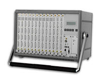
Digital Access System
K5302 DASY. This product is no longer sold
This product is no longer sold by Tektronix. Contact NetScout for more information.
Features & Benefits
- Digital Multiplexer to Concentrate PCM Signaling Timeslots
- Duplication of Timeslots Possible
- Supports E1 and DS1
- Can be Used and Configured Stand Alone
- Powerful Application to Control Several DASYs Available (Directly via RS-232 or Remotely via Modem or LAN IEEE 803.2)
- Clock Supply: Internal, External, PCM Link
- Designed to Enhance the Capabilities of Protocol Testers
- Support of time-synchronized couplings – allows coupling of logical links on Gb interface in GPRS networks
Applications
- Provide Protocol Testers with Flexible and Convenient Access to Test Environment with Many Links to be Analyzed
- Concentrate PCM Signaling Timeslots to Enhance Capabilities of Protocol Testers
- Duplicate Signaling Timeslots/PCM Links to Make the Same Signaling Available for Several Users
Functional Description
The K5302 DASY (Digital Access System) is a multiplexer for E1 and DS1 PCM lines. It consists of a mainframe, a control unit (DRC) with display, a power supply and a number of input and output boards. DASY's main function is to couple single timeslots or PCM streams from an input board to one or more output boards. With the latest Firm- and Software the DASY also supports the coupling of groups of timeslots, which will have exactly the same delay when coupled through the DASY.
The K5302 mainframe offers 13 slots to be used by input (DDM) or output (DDA) boards. Any combination of boards is possible, however, at least 1 input and 1 output board are required. As each DDM module can handle up to 8 bi-directional PCM lines (either E1 or DS1), the configuration with 12 DDM boards and 1 DDA board would offer a maximum of 96 incoming PCM lines to be connected to the DASY. The remaining DDA board would offer 4 Tx/Tx (8 Rx/Tx respectively) PCM lines. Each of the 2076 input timeslots (96*31, TS 0 to be handled separately) can be coupled to any of the output timeslots.
In order to increase the overall capacity of the system, several DASYs may be cascaded.
Fields of Application
The K5302 has been designed for various purposes:
- To provide protocol testers with flexible and convenient access to a test environment with a huge number of links to be analyzed
Testing under lab conditions often means analyzing different interfaces. The configurations and thus the cabling often change. After connecting all possible PCM links to the multiplexer, DASY offers an easy way to couple the appropriate input links to the output.
- To concentrate PCM signaling timeslots in order to enhance capabilities of protocol testers such as the K1205
The number of physical PCM interfaces of a protocol tester is usually limited. On the other hand, it is quite common that only very few (even just one) timeslots of a PCM link are used for signaling purposes. By multiplexing single timeslots of several links to one output PCM link DASY offers a solution to solve this contradiction.
- To duplicate signaling timeslots/PCM links in order to make the same signaling available for several users
It is not unusual for certain PCM links to be of interest to different users working with different analyzers. Connecting a number of protocol testers to a PCM link may have an impact (due to impedance reasons) on this link. As the DASY offers a convenient way to duplicate single timeslots or even PCM links, it will make the same link available for several users without degrading the performance of the PCM links.
In order to avoid operating errors when setting couplings, a 4 digit PIN can be assigned to each output connector. If the password protection is turned on, users can only set/reset couplings on output connectors they have logged into before. To control the configuration of PINs, the user must have a Master PIN. Couplings may be stored in an EEPROM and will then automatically be restored after a power outage.
Modes of Operation
DASY can be operated in 3 modes:
- Stand Alone - The complete set of features of the DASY can be used without any additional hardware or software*1. A 20*4 character LCD provides an intuitive menu to operate DASY with only 5 keys. This mode of operation should be used for quasi-static configurations.
- With DASY Remote Control SW - If more frequent changes of the coupling matrix are required, the remote control application, which comes with the DASY, should be used. This application runs under Windows NT/95/98/ME/2000/XP and provides an easy to use interface. The PC running this application can be connected via RS-232 and/or LAN (IEEE 802.3, RJ-45) interface to the DASY. Besides using a direct serial connection via RS-232 (data rates 1,200 to 19,200 b/s), it is possible to connect a modem to the DASY and dial in remotely. With the LAN interface it is even possible to control the DASY using the Internet as a transport media.
- From a User Application - Tektronix offers a Control C Library for Windows NT/95/98/ME/2000/XP, which provides a well defined API (application programming interface). It enables a user to control the DASY from a user application. This library supports the serial interface as well as the LAN interface and gives full access to DASY's functionality. By using this API, it is possible to set up to 4 couplings per second. DASY can handle up to 10 TCP/IP connections simultaneously.
*1 Grouped Couplings can only be set up, modified, and deleted using the Remote Control Software.
DASY Remote Control Application
Figure 1. DASY Overview.
The easiest way to operate the DASY is the remote control application. This software is able to control an unlimited number of DASYs regardless whether the units are connected directly via a serial cable, via a modem or a LAN connection (see Figure 1). A Microsoft Explorer-like tree structure offers an easy way to navigate through the different DASYs and their input and output boards. The software automatically detects the hardware and firmware versions of the DASY connected to it, and can thus also control elder units. This software offers the following functions:
- Easy setup of couplings
- Couplings are displayed in a tabular format
- Each coupling can be assigned a specific name which will be stored (see Figure 2)
- The complete configuration can be stored and later retrieved
- The coupling scheduler provides a simple way to define time limited couplings (see Figure 3)
- Configure impedance, framing mode and line code of DDM-2 and DDA-2 modules
- Configure IP address and port as well as the serial parameters (baud rate) for the DRC-2 modules
- DASY Remote Control SW displays receiver alarms (overview and details) of all DASYs (see Figure 4)
- Configuration/Administration can be automated using a simple scripting language
New:
- Support of time-synchronized couplings (“Group Couplings”)
- Status Display of internal resources (Figure 5)
- Improved synchronization between resources in DASY and Remote Control Software
- Export of DASY configuration and coupling information to CSV file (for further usage in spreadsheet and database applications)

Figure 2. Add a new coupling.

Figure 3. Working with the coupling scheduler.

Figure 4. Display of DASY receiver alarms.

Figure 5. Status Display of internal resources.
Application Examples
Figure 6 shows a quite common configuration: Several PCM links are connected to the DASY input. DASY extracts the SS7 signaling channels (TS 16) from these links and concentrates them into a single PCM link.

Figure 6. Typical DASY configuration.
This link is duplicated and connected to the input of 2 K1205 Protocol Testers. The couplings of the DASY are set up on a separate PC that is connected to the DASY via LAN.

Figure 7. Remote DASY connected via leased lines.
If the DASY is not at the same site as the Protocol Testers, leased lines can be used to provide the connection between the units as illustrated in Figure 7. While protocol testers are usually fed with a PCM link, which contains a (Tx-) signal in both directions, the leased line equipment usually needs a normal Rx/Tx pair on both ends of the leased line. The DASY output (DDA) boards provide 2 Rx/Tx pairs per connector (8 in total) and can be placed on both ends of the leased line. The incoming links at the protocol tester site can be coupled to any other DDA board in order to provide the protocol tester with the normal Tx/Tx link. Of course there can be other incoming links connected to the input boards of the DASY. The couplings of the DASY can be configured via a modem connection.
Note: The back direction of the leased line (tester => remote site) is not used to transfer any signaling data but is needed to run the leased line properly.
Characteristics
Clock Supply
Rx Clock - The control processor scans all interfaces for a valid signal. The clock of the first interface found with a correct signal will be used as the system clock.
External - A 2 MHz clock as per ITU-T Recommendation G.703 must be fed into the DRC module and is then used as the system clock.
Internal - The system clock is generated internally.
Technical Data of the 2 Mbit/s modules
Interface conditions as per ITU-T Recommendation G.703.
|
Mode |
E1 |
DS1 |
|---|---|---|
|
Bit rate |
2,048 kb/s |
1,544 kb/s |
|
Line code |
HDB3, AMI |
B8ZS, AMI |
|
Input impedance |
120 Ω, 75 Ω, >3 kΩ |
100 Ω, >3 kΩ |
|
Frame formats |
double frame, |
12-frame multiframe (F12), |
|
CRC multiframe |
24-frame multiframe (FS24) = extended super frame (ESF) |
|
|
Input voltage |
150 mV to 3 V |
150 mV to 3 V |
|
Jitter tolerance |
better than ITU-T G.823 |
better than ITU-T G.823 |
|
Transmit Level*1 |
3 V at 120 Ω |
3 V at 100 Ω |
*1 Only valid for Output (DDA) module.
Note: The mode (E1/DS1) can be changed with a DIP-switch on the board. Line code, impedance and frame format can be configured via menu or software.
Detectable Alarms (indicated by different flashing period of LEDs) - Loss of Signal (LOS), Alarm Indication Signal (AIS), Loss of Frame (LOF), Remote Alarm Indication (RAI).
General Data
Power Supply
Protection Class: Safety Class 1 (protective ground).
Mains Input - Rated range of use - AC 100 to 240 V ±10%.
Line Frequency - Rated range of use 50/60 Hz -6% to +5%
Output Voltage - DC 5 V, 16 A.
Power Consumption - 145 VA MAX (fully equipped).
Fuse - 1.6 AT, 250 V, Type: IEC 5 x 20 mm
Certifications and Compliance
CB certificate according IEC61010-1 -
EU : CE mark - In accordance with EMC : 89/336EEC - EN61326 class A
LVD : 73/23EEC & 93/68EEC- EN61010-1 ed.1/A2
US and Canada Certification - In accordance with 61010B-1, First Edition, CAN/CSA C22.2 No.1010.1-92
Australia & New Zealand, CTICK - AS/NZS 2064.1/2
Protection Class - Safety Class 1.
Environmental Conditions
Ambient Temperature
Ambient temperature - +23 °C ±5% (with 55% humidity)
Operating Range - +5 °C to +40 °C (less than 85% humidity, without condensation).
Transportation/Storage - -20 °C to +55 °C.
Barometric pressure - 101.3 kPa (1013 mbar)
Altitude - 2000 m, maximum operating
Pollution degree - Pollution degree 2 (as defined in IEC61010-1). Note: Rated for indoor use only
Physical Characteristics
|
Dimensions |
mm |
in. |
|---|---|---|
|
Weight |
kg |
lbs. |
|
Width |
450 |
17.7 |
|
Height |
315 |
12.4 |
|
Depth |
311 |
12.2 |
|
Basic unit with handle |
12 |
26.5 |
|
Fully equipped |
17 |
37.5 |
Ordering Information
Digital Access System DASY-2 (UL)
Mainframe with display and control unit, 13 slots for input and output modules, RS-232 and Ethernet interface for remote control; 100 to 250 V auto-range power supply; Remote Control SW 7KK5302-8AB11; manual (German/English); Requirement: at least 1 input and 1 output module are needed to run the system. (Please order separately).
Order: 7KK5302-1UA01.
DRC-2 Upgrade (RS-232 and Ethernet)
Upgrades a DASY (shipped before May 2000) with a LAN interface; includes Remote Control SW 7KK5302-8AB11, manual (German/English); Requirement: DASY or DASY-2 mainframe (7KK5302-1Sxxx or 7KK5302-1Lxxx).
Order: 7KK5302-1DR11.
Input Modules
Input Module (DDM-2) for E1/DS1 Links - Impedance, line code, frame format configurable by software, pre-installed in mainframe, E1 pre-configured.
Order: 7KK5302-2MA01.
Input Module (DDM-2) for E1/DS1 Links - Impedance, line code, frame format configurable by software, pre-installed in mainframe, DS1 pre-configured.
Order: 7KK5302-2MA02.
Input Module (DDM-2) for E1/DS1 Links - Impedance, line code, frame format configurable by software, separate delivery, E1 pre-configured.
Order: 7KK5302-2MA11.
Input Module (DDM-2) for E1/DS1 Links - Impedance, line code, frame format configurable by software, separate delivery, DS1 pre-configured.
Order: 7KK5302-2MA12.
Output Modules
Output Module (DDA-2) for E1/DS1 Links - Impedance, line code, frame format configurable by software, pre-installed in mainframe, E1 pre-configured.
Order: 7KK5302-2SB01.
Output Module (DDA-2) for E1/DS1 Links - Impedance, line code, frame format configurable by software, pre-installed in mainframe, DS1 pre-configured.
Order: 7KK5302-2SB02.
Output Module (DDA-2) for E1/DS1 Links - Impedance, line code, frame format configurable by software, separate delivery, E1 pre-configured.
Order: 7KK5302-2SB11.
Output Module (DDA-2) for E1/DS1 Links - Impedance, line code, frame format configurable by software, separate delivery, DS1 pre-configured.
Order: 7KK5302-2SB12.
Cables
Cable for Input Module (DDM) - Balanced (120 Ω) with open ends, 4 pieces. Length: 5 m.
Order 7KK5302-5AA01.
Cable for Input Module (DDM) - Balanced (120 Ω) with open ends, 4 pieces. Length: 6 m.
Order 7KK5302-5AB01.
Cable for Input Module (DDM) - Balanced (120 Ω) with open ends, 4 pieces. Length: 10 m.
Order 7KK5302-5AC01.
Cable for Input Module (DDM) - Unbalanced (75 Ω) with open ends, 4 pieces. Length: 5 m.
Order 7KK5302-5AA02.
Cable for Input Module (DDM) - Unbalanced (75 Ω) with open ends, 4 pieces. Length: 6 m.
Order 7KK5302-5AB02.
Cable for Input Module (DDM) - Unbalanced (75 Ω) with open ends, 4 pieces. Length: 10 m.
Order 7KK5302-5AC02.
Conversion of One Set of Unbalanced DDM Cables with Open Ends (7KK5302-5Axx2) to Coax 1,6/5,6 - Note: If ordered 7KK5302-5Axx2 together with 7KK5302-5AX01 a complete set of cables for a DDM board will be shipped.
Order 7KK5302-5AX01.
Conversion of One Set of Unbalanced DDM Cables with Open Ends (7KK5302-5Axx2) to Coax Type 43 (BT) - Note: If ordered 7KK5302-5Axx2 together with 7KK5302-5AX02 a complete set of cables for a DDM board will be shipped.
Order 7KK5302-5AX02.
Cable for Output Module (DDA) - Balanced (120 Ω) with DB 9 male connector suitable for K1205, 4 pieces. Length: 5 m.
Order 7KK5302-5BA01.
Cable for Output Module (DDA) - Balanced (120 Ω) with DB 9 male connector suitable for K1205, 4 pieces. Length: 6 m.
Order 7KK5302-5BB01.
Cable for Output Module (DDA) - Balanced (120 Ω) with DB 9 male connector suitable for K1205, 4 pieces. Length: 10 m.
Order 7KK5302-5BC01.
Cable for Output Module (DDA) - Unbalanced (75 Ω) with open ends, 4 pieces. Length: 5 m.
Order 7KK5302-5BA02.
Cable for Output Module (DDA) - Unbalanced (75 Ω) with open ends, 4 pieces. Length: 6 m.
Order 7KK5302-5BB02.
Cable for Output Module (DDA) - Unbalanced (75 Ω) with open ends, 4 pieces. Length: 10 m.
Order 7KK5302-5BC02.
Cable DDA (2 DB 15 Male Connectors) to DDM (DB 15 Male Connector) - For DASY cascading, 1 piece. Length: 1.5 m.
Order 7KK5302-5CA01.
Cable DDA (2 DB 15 Male Connectors) to DDM (DB 15 Male Connector) - For DASY cascading, 1 piece. Length: 5 m.
Order 7KK5302-5CB01.
Cable DDA (2 DB 15 Male Connectors) to DDM (DB 15 Male Connector) - For DASY cascading, 1 piece. Length: 10 m.
Order 7KK5302-5CC01.
Rackmount Kit
Mounting Kit for 19 in. Rack - Order 7KK5302-5DA01.
Software
DASY Remote Control Software - For Windows NT/95/98/ME/2000/XP. Order 7KK5302-8AB11.
DASY Control C Library - Offers a C, C++ compatible API for controlling DASY from a user application. Order 7KK5302-8BA11.

Product(s) are manufactured in ISO registered facilities.
2FW-14215-2

