
联系我们
与泰克代表实时聊天。 工作时间:上午 9:00 - 下午 5:00(太平洋标准时间)。
电话
致电我们
工作时间:上午9:00-下午5:00(太平洋标准时间)
下载
下载手册、产品技术资料、软件等:
反馈
极限和掩模测试应用软件产品技术资料
Option LT, MTH, MTM产品技术资料
Features & Benefits
Option LT – Limit Test Application Software
- Conduct Limit Test Pass/Fail Testing against a “Golden” Waveform with Tolerances
- Customized Limit Tests allow for Multiple Actions upon Test Failures
- Designed for use on MSO/DPO5000, DPO7000, and MSO/DPO70000 Series Oscilloscopes
Option MTH – Mask Test Application Software
- Perform Pass/Fail Testing against Telecommunication and Computer Standards
- Customized Mask Tests allow for Multiple Actions upon Test Failures
- Detailed Test Statistics provide Insight into True Signal Behavior
- Designed for use on MSO/DPO70000 Series Oscilloscopes (standard on the MSO70000 Series)
Option MTM – Mask Test Application Software
- Perform Pass/Fail Testing against Telecommunication and Computer Standards
- Customized Mask Tests allow for Multiple Actions upon Test Failures
- Detailed Test Statistics provide Insight into True Signal Behavior
- Designed for use on MSO/DPO5000 Series and DPO7000 Series Oscilloscopes
Applications
- Pass/Fail Testing
- ITU-T
- ANSI T1.102
- SONET/SDH
- 100BASE-TX, 1000BASE-CX/SX Ethernet
- CPRI
- USB 1.1/2.0
- Fibre Channel
- OBSAI
- InfiniBand
- Serial ATA
- SAS
- IEEE1394b
- Rapid IO
- OIF
- Video Standards
Automated Pass/Fail Testing
Validating signal quality is an important part of any embedded system design. One way to determine how well your signals conform to expected signal quality is to use mask testing. A mask defines a portion, or portions, of the oscilloscope display that a signal must not enter.
The Limit Test Application Software (Option LT) makes it easier to validate how your signals are performing compared to a known good condition.
The Mask Test Application Software (Options MTH and MTM) enables testing against a well-defined telecommunication or computer standard providing automated statistical analysis of signal quality.
Option LT – Limit Test Application Software
A common method for understanding your signal quality is to compare against a known good or “golden” waveform. You can apply horizontal and vertical tolerances to the golden waveform to create a template that can be used for quick, accurate Pass/Fail testing. This method is also a great way to perform go/no-go testing on a manufacturing line by enabling repeatable, fast decisions on the quality of a component or system. The Limit Test Application Software allows you to save your limit test template for use later across multiple oscilloscopes in a lab or on a production line.
The Limit Test Application Software will highlight any waveform samples that fall outside of the limit test template, providing you with quick visual evidence of a failure.
Limit test finds infrequent glitches and runt signals using a mask created by adding vertical and horizontal tolerances around a golden waveform. Test your signals against a golden waveform and quickly gain insight into anomalous behavior.
When a test failure is detected, the oscilloscope can perform a number of actions in parallel. These actions include stopping the acquisition, e-mailing a message indicating the test has failed, saving a waveform to a file, logging the date and time to a file, printing the waveform, and sending a GPIB SRQ command.
Option MTH, MTM – Mask Test Application Software

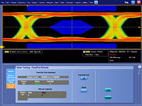
OC12 (622.5 Mb/s) standard mask showing results from a mask test. A robust set of telecommunications and computer industry standard masks make testing to standards quick and accurate.
When it is necessary to measure performance of your signals against telecommunications or computer standards to verify compliance and interoperability, the Mask Test Application Software, with more than 100 standard masks, makes it easy. Each standard mask is easily loaded from the oscilloscope internal memory and can be immediately used to conduct Pass/Fail testing. Adherence to a standard mask is determined pixel-by-pixel throughout the display.
When a standard mask is loaded, the oscilloscope makes use of the integrated Communication Trigger. Each standard mask is associated with a communication standard and the mask you select automatically determines which communication trigger is used. Some models include integrated clock recovery circuitry up to 6 Gb/s for NRZ eye patterns. Clock recovery allows you to perform more reliable and accurate mask testing.
The oscilloscope can reduce setup time for making a mask test measurement by performing an Autoset for vertical, horizontal, and trigger parameters on the source signal. Additionally, to reduce the chance of failures, the oscilloscope can Autofit the waveform to the mask to minimize hits within the mask. It can do this a single time following an Autoset or it can perform an Autofit after every triggered acquisition.

The Mask Test Application Software enables multiple actions upon a test failure or the completion of a test, tailoring the test to your specific needs.
The Mask Test Application Software provides flexible test definitions enabling you to tailor the test to your needs. You can run a test for a user-defined number of waveforms (up to 2.14×10⁹). The Repeat Test and Pretest Delay capability enables swapping of test locations before proceeding with a test over multiple cycles of the test. You can set the number of violations that can occur before a test status is considered failed. The oscilloscope can also perform a number of actions when a test fails or completes. Actions the oscilloscope can perform when a test fails include stopping the acquisition, e-mailing a message indicating the test has failed, saving a waveform to file, logging the date and time of the failure, printing a waveform, sending a GPIB SRQ, and sending a trigger out pulse. Actions the oscilloscope can perform when a test completes include sending a GPIB SRQ and sending a trigger out pulse.

Detailed mask test results show statistical information for the test. The results include information on test sample size, failures, total number of hits, and the number of hits in each mask segment.
The Mask Test Application Software provides statistical results from each test conducted. The results include Pass/Fail status of the test, number of waveforms/samples tested, number of violations found, and the total number of hits within the mask. A secondary display shows the total number of hits in each segment of the mask providing further insight into any mask violations.
Characteristics
Option LT – Limit Test Characteristics
Characteristic | Description |
|---|---|
Test Source | Any Ch1 – Ch4, Math1 – Math4, R1 – R4 |
Template Storage | Limit test template can be saved into any R1 – R4 location or to a file |
Template Creation Margins | Vertical tolerance from 0 to 5 divisions in 0.1m (1/10,000th) division increments Horizontal tolerance from 0 to 5 divisions in 0.1m (1/10,000th) division increments Note: Use Average acquisition mode to help create a smoother limit test template |
Lock Template to Waveform | Lock ON: Template automatically re-scales with source channel settings changes Lock OFF: Template does not re-scale with source channel settings changes |
Highlight Hits | Highlight Hits ON: Visually highlight any samples that fall outside of the limit test template Highlight Hits OFF: Samples that fall outside of the limit test template are not visually highlighted |
Limit Test Status | Passed: No samples from the test source have fallen outside of the limit test template Failed: At least one sample from the test source has fallen outside of the limit test template |
Limit Test Control | ON: Limit test is active and hits are being tracked OFF: Limit test is not active and hits are not being tracked |
Reset | Clears all violations in preparation for another test |
Actions on Limit Test Failure | Stop Acq: When Stop Acq is ON, the instrument stops acquiring if a limit test fails Beep*1: When Beep is ON, the instrument beeps if a limit test fails E-mail: When E-mail is ON, the instrument sends an e-mail if the limit test fails Save Waveform: When Save Wfm is ON, failed waveform data is saved to a file Log Date: When Log Date is ON, the date and time for each failed limit test is recorded to a file Print: When Print is ON, the instrument sends the waveform to a printer if a limit test fails SRQ: When SRQ is ON, the instrument sends a GPIB SRQ command if a limit test fails |
*1 Not available on MSO/DPO5000 Series.
Option MTH, MTM – Mask Test Characteristics
Characteristic | Description |
|---|---|
Test Source | Any Ch1 – Ch4, M1 – M4, R1 – R4 |
Mask Creation | Select standard mask from internal memory Load custom mask from text file with up to 16 mask segments Copy a standard mask to user mask and edit |
Included Standard Mask Types | The standards available vary by model depending on the bandwidth and configuration of the instrument |
ITU-T | DS0 Single (64 kb/s) DS0 Double (64 kb/s) DS0 Data Contra (64 kb/s) DS0 Timing (64 kb/s) DS1 Rate (1.544 Mb/s) E1 Sym Pair (2.048 Mb/s) E1 Coax Pair (2.048 Mb/s) Clk Intf. Sym (2.048 Mb/s) Clk Intf. Coax (2.048 Mb/s) DS2 Rate Sym (6.312 Mb/s) DS2 Rate Coax (6.312 Mb/s) E2 (8.448 Mb/s) 32Mb (32.064 Mb/s) E3 (34.368 Mb/s) DS3 Rate (44.736 Mb/s) 97Mb (97.728 Mb/s) E4 Binary 0 (139.26 Mb/s) E4 Binary 1 (139.26 Mb/s) STM1E Binary 0 (155.52 Mb/s) STM1E Binary 1 (155.52 Mb/s) STM-0 HDBx (51.84 Mb/s) STM-0 CMI 0 (51.84 Mb/s) STM-0 CMI 1 (51.84 Mb/s) |
ANSI T1.102 | DS1 (1.544 Mb/s) DS1A (2.048 Mb/s) DS1C (3.152 Mb/s) DS2 (6.312 Mb/s) DS3 (44.736 Mb/s) DS4NA (139.26 Mb/s) DS4NA Max Output (139.26 Mb/s) STS-1 Pulse (51.84 Mb/s) STS-1 Eye (51.84 Mb/s) STS-3 (155.52 Mb/s) STS-3 Max Output (155.52 Mb/s) |
SONET/SDH | OC1/STM0 (51.84 Mb/s) OC3/STM1 (155.52 Mb/s) OC12/STM4 (622.08 Mb/s) OC48/STM16 (2.4883 Gb/s) OC48/STM16 FEC (2.666 Gb/s) |
Ethernet | 100BASE-TX STP (125 Mb/s) 100BASE-TX UTP (125 Mb/s) 1000B-SX/LX/PX (1.25 Gb/s) 1000B-CX Norm, TP2 (1.25 Gb/s) 1000B-CX Abs, TP2 (1.25 Gb/s) 1000B-CX Abs, TP3 (1.25 Gb/s) XAUI, Near (3.125 Gb/s) XAUI, Far (3.125 Gb/s) |
CPRI (Common Public Radio Interface) | CPRI1228 (1.228 Gb/s) CPRI2457 (2.457 Gb/s) CPRI3072 (3.072 Gb/s) |
USB 1.1/2.0 | FS (12 Mb/s) HS:T1 (480 Mb/s) HS:T2 (480 Mb/s) HS:T3 (480 Mb/s) HS:T4 (480 Mb/s) HS:T5 (480 Mb/s) HS:T6 (480 Mb/s) |
Fibre Channel | FC133 Optical (132.8 Mb/s) FC266 Optical (265.62 Mb/s) FC531 Optical (531.25 Mb/s) FC1063 Optical (1.0625 Gb/s) FC1063 Optical Draft Rev 11 FC2125 Optical (2.125 Gb/s) |
Fibre Channel Electrical | FC133E Elec. (132.8 Mb/s) FC266E Elec. (265.62 Mb/s) FC531E Elec. (531.25 Mb/s) FC1063E Elec. (1.0625 Gb/s) FC1063E Norm, Beta, Transm FC1063E Norm, Delta, Transm FC1063E Norm, Gamma, Transm FC1063E Abs, Beta, Transm FC1063E Abs, Delta, Transm FC1063E Abs, Gamma, Transm FC1063E Abs, Beta, Recv FC1063E Abs, Delta, Recv FC1063E Abs, Gamma, Recv FC2125E Norm, Beta, Transm FC2125E Norm, Delta, Transm FC2125E Norm, Gamma, Transm FC2125E Abs, Beta, Transm FC2125E Abs, Delta, Transm FC2125E Abs, Gamma, Transm FC2125E Abs, Beta, Recv FC2125E Abs, Delta, Recv FC2125E Abs, Gamma, Transm FC4250E Norm, Beta, Transm FC4250E Norm, Delta, Transm FC4250E Norm, Gamma, Transm FC4250E Abs, Beta, Transm FC4250E Abs, Delta, Transm FC4250E Abs, Gamma, Transm FC4250E Abs, Beta, Recv FC4250E Abs, Delta, Recv FC4250E Abs, Gamma, Recv |
OBSAI (Open Base Station Architecture Initiative) | OBSAI3072_Tx (3.072 Gb/s) OBSAI3072_Rx (3.072 Gb/s) OBSAI6144_Tx (6.144 Gb/s) OBSAI6144_Rx (6.144 Gb/s) |
InfiniBand | 2.5 Optical (2.5 Gb/s) 2.5 Electrical (2.5 Gb/s) |
Serial ATA | G1 Tx 5-Cycle (1.5 Gb/s) G1 Rx 5-Cycle (1.5 Gb/s) G2 Tx 5-Cycle (3.0 Gb/s) G2 Rx 5-Cycle (3.0 Gb/s) G3 Tx 5-Cycle (6.0 Gb/s) G3 Rx 5-Cycle (6.0 Gb/s) |
SAS | SAS IR (1.5 Gb/s) SAS CR (1.5 Gb/s) SAS XR (1.5 Gb/s) SAS IR, AASJ (1.5 Gb/s) SAS CR, AASJ (1.5 Gb/s) SAS XR, AASJ (1.5 Gb/s) SAS, SATA (1.5 Gb/s) SAS IR (3.0 Gb/s) SAS CR (3.0 Gb/s) SAS XR (3.0 Gb/s) SAS IR, AASJ (3.0 Gb/s) SAS CR, AASJ (3.0 Gb/s) SAS XR, AASJ (3.0 Gb/s) SAS, SATA (3.0 Gb/s) |
IEEE 1394b | S400b T1 (491.5 Mb/s) S400b T2 (491.5 Mb/s) S400ß Optical (491.5 Mb/s) S800b T1 (983.0 Mb/s) S800b T2 (983.0 Mb/s) S800 ß Optical (983.0 Mb/s) S1600b T1 (1.966 Gb/s) S1600b T2 (1.966 Gb/s) S1600ß Optical (1.966 Gb/s) |
Rapid IO LP-LVDS | Drv (500 Mb/s) Drv (750 Mb/s) Drv (1.0 Gb/s) Drv (1.5 Gb/s) Drv (2.0 Gb/s) Ext Drv (500 Mb/s) Ext Drv (750 Mb/s) Ext Drv (1.0 Gb/s) Ext Drv (1.5 Gb/s) Ext Drv (2.0 Gb/s) Rcv (500 Mb/s) Rcv (750 Mb/s) Rcv (1.0 Gb/s) Rcv (1.5 Gb/s) Rcv (2.0 Gb/s) |
Rapid IO Serial | RIO Serial (1.25 Gb/s) RIO Serial (2.5 Gb/s) RIO Serial (3.125 Gb/s) |
OIF Standards | SFI/SPI-5 TA Data (2.488 Gb/s) SFI/SPI-5 TC Data (2.488 Gb/s) SFI/SPI-5 TA Clk (2.488 Gb/s) SFI/SPI-5 TC Clk (2.488 Gb/s) SFI/SPI-5 RB Data (2.488 Gb/s) SFI/SPI-5 RD Data (2.488 Gb/s) SFI/SPI-5 RB Clk (2.488 Gb/s) SFI/SPI-5 RD Clk (2.488 Gb/s) SFI/SPI-5 TA Data (3.125 Gb/s) SFI/SPI-5 TC Data (3.125 Gb/s) SFI/SPI-5 TA Clk (3.125 Gb/s) SFI/SPI-5 TC Clk (3.125 Gb/s) SFI/SPI-5 RB Data (3.125 Gb/s) SFI/SPI-5 RD Data (3.125 Gb/s) SFI/SPI-5 RB Clk (3.125 Gb/s) SFI/SPI-5 RD Clk (3.125 Gb/s) VSR OC192/STM64 (1.24416 Gb/s) TFI-5 (2.488 Gb/s) TFI-5 (3.1104 Gb/s) |
PCI Express | PCI-Express Transm (2.5 Gb/s) PCI-Express Recv (2.5 Gb/s) |
Video | 4FSC NTSC "D2" (143.18 Mb/s) 4:4:2 "D1" (270Mb/s) DVB ASI (270 Mb/s) 4:2:2 SMPTE 259M-D (360 Mb/s) SMPTE 292M (1.485 Gb/s) |
Mask Polarity | This control is only displayed for certain mask types. Use this control to select Positive or Negative polarity for the mask |
Mask Display | ON: Mask display is on OFF: Mask will not be displayed |
Lock Mask to Waveform | Lock to Waveform ON: Mask automatically re-scales with source channel settings changes Lock to Waveform OFF: Mask does not re-scale with source channel settings changes |
Hit Counts | ON: Any hit in any mask segment will be counted and displayed in the Pass/Fail Test Summary OFF: Hits in mask segments will not be counted |
Highlight Hits | Highlight Hits ON: Visually highlight any samples that fall within a mask segment Highlight Hits OFF: Samples that fall inside of a mask segment are not visually highlighted |
Mask Alignment: Autoset | Use Mask Autoset to automatically align the source signal within the mask Parameters that can be used in the Mask Autoset procedure include: Vertical (Scale, Position, DC Compensation), Horizontal (Scale, Position), and Trigger Autoset Mode: Select Auto to have Autoset performed after a standard mask has been selected. Select Manual to make adjustments manually Autofit Once: The waveform is autofit once following an autoset |
Mask Alignment: Autofit | ON: The waveform is autofit to the mask and will minimize hits within the mask on each acquisition OFF: The waveform will not be autofit to the mask on each acquisition Controls for setting the vertical and horizontal maximum levels of adjustment are available |
Mask Margin Tolerance | ON: The percentage of margin used in the mask test is user-controllable OFF: The percentage of margin used in the mask test is not user-controllable Range: –50% to +50% in 1% increments; A margin of <0% moves mask segments further apart, making a mask test easier to pass. A margin of >0% moves mask segments closer together, demonstrating that the signal passes the test with margin for further error |
Test Criteria Run Until | Minimum number of samples (from 5,000 to 2.14×10⁹) when in WfmDB acquisition mode. Minimum number of waveforms (from 1 to 2.14×10⁹) in all other acquisition modes |
User Mask Edit | Modify a User Mask through an intuitive graphical user interface Select a mask segment and vertex to edit, and then set the horizontal and vertical values Add or delete segments in an existing mask or vertices in an existing mask segment Save a mask to a file, or recall a mask from a file |
Pretest Delay | From 0 s to 60 s |
Fail Threshold | From 1 to 2.14×10⁹ |
Pass/Fail Test Control | ON: Test is started and runs until completed or manually stopped OFF: Test is not running |
Repeat on Completion | ON: Test will repeat when the minimum number of waveforms or minimum amount of time is reached OFF: Test will run a single time and will not repeat |
Mask Polarity | Positive, Negative, or Both. Test will complete with the selected mask polarity. When Both is selected the test will run with Positive polarity and with Negative polarity |
Actions on Mask Test Failure | Stop Acq: When Stop Acq is ON, the instrument stops acquiring if a mask test fails Beep*1: When Beep is ON, the instrument beeps if a limit test fails E-mail: When E-mail is ON, the instrument sends an e-mail if the limit test fails Save Waveform: When Save Wfm is ON, failed waveform data is saved to a file Log Date: When Log Date is ON, the date and time for each failed limit test is recorded to a file Print: When Print is ON, the instrument sends the waveform to a printer if a limit test fails SRQ: When SRQ is ON, the instrument sends a GPIB SRQ command if a limit test fails AUX Out*1: When AUX Out is ON, the instrument sends a trigger to the Auxiliary Out connector when a mask test fails |
Actions on Mask Test Complete | Beep*1: When Beep is ON, the instrument beeps when the mask test is complete SRQ: When SRQ is ON, the instrument sends a GPIB SRQ command when the mask test is complete AUX Out*1: When AUX Out is ON, the instrument sends a trigger to the Auxiliary Out connector when a mask test is complete |
Pass/Fail Results Display | Pass/Fail Test Summary: Includes information on the outcome of a test Samples Tested: Shows the current number of samples tested out of the total number to be tested Source: Indicates what signal source was used for the test Status: Indicates whether the test has Passed, Failed, or is Passing Total Hits: The total number of data points that violated the mask Failed Wfms: The total number of waveforms that failed during the test Hits per Segment: The number of hits that have violated each segment in the mask |
*1 Not available on MSO/DPO5000 Series.
Ordering Information
Limit Test Application Software
Model | New Instrument Orders | Product Upgrades | Floating Licenses |
|---|---|---|---|
MSO/DPO5000 Series | Opt. LT | DPO-UP Opt. LT | DPOFL-LT |
DPO7000 Series | Opt. LT | DPO-UP Opt. LT | DPOFL-LT |
MSO/DPO70000 Series | Opt. LT | DPO-UP Opt. LT | DPOFL-LT |
Mask Test Application Software
Model | New Instrument Orders | Product Upgrades | Floating Licenses |
|---|---|---|---|
MSO/DPO5000 Series | Opt. MTM | DPO-UP Opt. MTM | DPOFL-MTM |
DPO7000 Series | Opt. MTM | DPO-UP Opt. MTM | DPOFL-MTM |
DPO70000 Series | Opt. MTH | DPO-UP Opt. MTH | DPOFL-MTH |
MSO70000 Series | Standard | Standard | Standard |
Recommended Probes
Please refer to www.tek.com/probes for further information on the recommended models of probes and any necessary probe adapters. |

Tektronix is registered to ISO 9001 and ISO 14001 by SRI Quality System Registrar.
61W-26237-3

