Introduction
The worldwide battery market is undergoing enormous growth, due in large part to recent advances in electronic technology. The growing list of battery applications includes cellular phones, pagers, hearing aids, electric vehicles, and satellites. Batteries are used in a variety of consumer and industrial applications, so their testing requirements typically depend on their chemistry, size, and specific uses. Secondary (rechargeable) batteries are commonly tested using discharge-and-charge cycling. The discharge characteristics of a secondary battery provide important indications of the battery’s capacity and life. In production testing, a discharge/charge cycle is often run to verify battery quality and to ensure it is not short-circuited.
A typical battery discharge-and-charge test set-up includes programmable power supplies, electronic loads, voltmeters, and ammeters. This application note describes how Keithley Series 2400 SourceMeter instruments can be substituted for a number of separate instruments. Since the instruments in the 2400 Series can source and measure both current and voltage, only one instrument is needed for cycle testing, which reduces the amount of rack space required and minimizes programming time. This application note also describes discharge and charge methods, discharging using pulsed current (including an example specifically for GSM cellular phones), and testing multiple batteries. Example programs for automating battery discharge are also provided.
Test Description
Secondary batteries may be charged/discharged using a variety of methods, depending on the application. This application note describes how to do so using either a constant voltage source or a constant current source.
In the constant voltage method, a programmable voltage source supplies a fixed voltage that's equivalent to the voltage rating of the battery. The current of the voltage source is limited to a safe charging rate. As the battery becomes fully charged, the current will decrease until it reaches zero or near zero. To prevent safety hazards or damage to the battery, care must be taken not to overcharge the battery. Discharging a battery to levels below its specified voltage rating can result in longer charge time or may damage the battery.
Batteries can also be charged using a constant current. With this method, a programmable current source supplies a constant current. The current source will continue discharging or charging the battery until it reaches a preprogrammed voltage level.
Rates for constant current discharging or charging are defined in terms of the battery's capacity (C). The capacity of the battery is defined as the time integral of the current flow out of the battery from the beginning of the current flow (t=0) to a time when it reaches a specified cut-off voltage, and can be expressed as:
Capacity = ∫Δtidt
The capacity is specified in terms of ampere-hours and should be expressed in terms of a load current. For example, a 500 milliampere-hour cell, discharged at 50mA, is discharged at the 0.1C or C/10 rate. This battery, with a capacity of 500mAh @ 50mA, could supply a 10mA load for 50 hours. Factors affecting capacity include battery size, chemistry, temperature, discharge rate, open circuit time, etc. The charge rates will vary depending on the application.
Test Procedures
Discharging/Charging Using a SourceMeter Instrument as a Constant Voltage Source
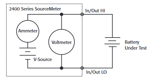
Figure 1 illustrates a battery connected to the SourceMeter instrument. While the instrument is in the constant voltage mode, it can measure either current or voltage. The voltage source value is set to the desired level to which the battery will ultimately be charged or discharged. The compliance current is set at an appropriate level at which to charge and/or discharge for that battery type. As the instrument is either charging or discharging the battery to the desired voltage level, the instrument will be in current compliance until it reaches the programmed voltage level. While the instrument is in current compliance, it is actually acting as a constant current source. The front panel CMPL indicator will flash while in compliance.
Discharging/Charging Using the SourceMeter Instrument as a Constant Current Source
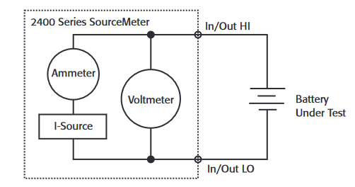
As shown in Figure 2, a SourceMeter instrument can measure either current or voltage while in the constant current source mode. The instrument is set up by first selecting the proper current output value. When charging, a positive test current is used; when discharging, a negative test current is used. The setting of the compliance voltage will depend on whether the battery is being charged or discharged.
For charging only, the compliance voltage is set to the desired battery voltage level. Once the source output is turned on, the instrument will output a constant current until it reaches the predetermined voltage level. At that point, the instrument will go into compliance and become a constant voltage source. This will be indicated by a flashing CMPL annunciator on the instrument’s front panel display.
For discharging, the compliance voltage is always set higher than the nominal voltage of the battery. It should never be set lower than the battery voltage because the instrument will go into compliance, causing the output current to be much higher than desired. Under computer control, the battery voltage can be measured by the instrument, then compared to the desired threshold level.
CAUTION: When using a SourceMeter instrument for sourcing current to charge and/or discharge batteries, make sure the battery voltage never exceeds the voltage compliance setting because this will cause excessive current to be drawn from the battery under test. Also, be certain the output-off state of the current source is set for HIGH-IMPEDANCE (HI-Z). This setting opens the output relay when the output is turned off. With the NORMAL output-off state selected (the default condition), turning the output off sets the voltage compliance to zero. This zero volt compliance condition will cause excessive current to be drawn from the external battery.
The HIGH-IMPEDANCE output-off state can be selected from the front panel by pressing CONFIG, then the OUTPUT button. Select OFF-STATE using the arrow keys and press ENTER. Select HIGH-IMPEDANCE and press ENTER. Press EXIT once to return to the main display. Over the bus, the HIGH-IMPEDANCE mode can be selected by sending the command :OUTP:SMOD HIMP.
Automating the Discharge Cycle
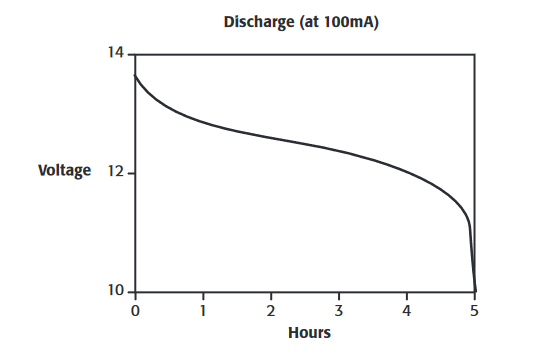
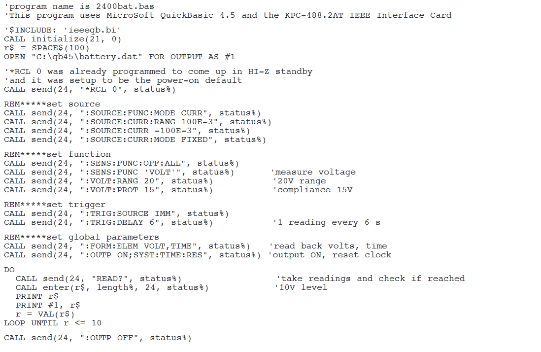
Charge and discharge cycles often take several hours to complete, making it desirable to automate these tests with a computer and programmable instrumentation. Because SourceMeter units have built-in IEEE-488 interfaces, the charge/discharge cycling of the batteries can be automated using a personal computer with its own IEEE-488 interface. The following program, 2400BAT. BAS, instructs the instrument to discharge a 12V battery to 10V using a 100mA current load. One voltage reading is taken every six seconds, which is then stored in a data file (BATTERY.DAT), along with a corresponding time-stamp reading. This stored data makes it possible to plot voltage vs. time for the discharge cycle. As the voltage readings are being taken, they are compared with the 10V threshold level. When this level is reached, the output is turned off.
Figure 3 shows an example plot of data taken while a 12V battery was being discharged. Both the voltage and time readings were generated using the SourceMeter instrument, eliminating the need to program the computer timer. The data was plotted using Microsoft Excel.
IMPORTANT NOTE: Before running the program, the instrument must be turned on and the output must be set to the high impedance (HI-Z) mode. This will prevent the battery from draining when the battery is connected with the output off. Once the instrument is in the HI-Z mode, save this configuration as a stored setup at memory location 0. This is done using the instrument’s front panel controls by pressing the MENU key, then selecting SAVESETUP (ENTER), GLOBAL (ENTER), SAVE (ENTER), and 0 (ENTER). Over the bus, the proper command is *SAV 0. Program the instrument to power up with this configuration. From the front panel controls, this is done by first pressing MENU and then selecting SAVESETUP (ENTER), GLOBAL (ENTER), POWERON (ENTER), USERSETUP-NUMBER (ENTER), and 0 (ENTER). Over the bus, the command is :SYST:POS 0. When the program is run, it sends a *RCL 0, which recalls the setup at memory location 0, so there will not be a drain on the battery
Charging/Discharging Using a Pulsed Current
Some rechargeable batteries are used in applications in which the load current is a digital signal, such as cellular phones and pagers. For these types of applications, it is desirable to charge/discharge the battery using a pulsed current.
Pulsed waveforms can be created by the Series 2400 SourceMeter instruments by either changing the level of the fixed source output or by using Source List commands. The Source List feature is used if the desired pulsed output is less than about one second. If the desired pulsed output is greater than one second in length, it is better simply to change the output using the standard fixed source output commands. Two example pulsed source applications are described here.
Example #1: Pulsed Current Output and Voltage Monitoring using the SourceMeter Instrument
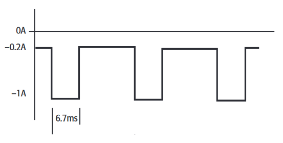
Figure 4 illustrates an example waveform. In this waveform, a peak current of -1A is applied for 6.7ms, then an idle current of -0.2A is applied for 13.3ms. The period is 20ms.
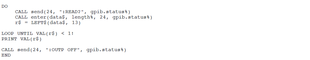
An example program (2400puls.bas) with the command sequence used to create this waveform is listed here. In this program, the voltage is measured during each source list location. This voltage is compared to a pre-specified level. Once the voltage reaches that level, the output current is turned off.
The Source List commands are used to define a list of up to 100 source values for the instrument. When the list is executed, the instrument outputs the values in the source list sequentially for the amount of time specified by the Source Delay command. One limitation of the source list is that each source value in the list must be output for the same length of time.
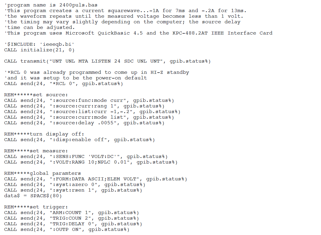
To create the output as shown in Figure 4, two (not three) Source List values are output, each for 6.7ms. The first location is set for –1A and the second output is set for –0.2A. The source delay time was set for 5.5ms, rather than 6.7ms, because software overhead time must be added to each step. This waveform can be repeated automatically for as long as desired. Also, additional software overhead or jitter is added to the final value in the list, so the last value will be on for a longer period of time. In this case, the overhead time is about 6ms. This GPIB overhead time is used to send the readings and parse the next read query. This time will vary, depending on the computer used. Setting up the exact waveform will take some adjusting of the time of the Source Delay command using an oscilloscope.
In some applications, the time limitation of the Source List may be a problem, especially if the test involves using an exact frequency. In other applications, however, the exact timing of the peak and idle current is not as critical as long as the average current draw of the battery is as specified.
IMPORTANT NOTE: Before running the program, the SourceMeter instrument must be in the Hi-Z mode, as described in the note at the end of the section entitled "Automating the Discharge Cycle."
Example #2: Testing Batteries Used for Cellular Phones Designed to the GSM Standard
Some battery testing applications require generating pulses of a few milliseconds or even a few hundred microseconds in length, such as the GSM call profile. For these applications, a SourceMeter instrument can output these pulsed waveforms; however, the instrument is unable to make the corresponding voltage measurement at the same time. In these applications, a second SourceMeter unit is required to make the voltage measurement. This set-up is illustrated in Figure 5, which shows a Model 2420 High-Current SourceMeter instrument generating a pulsed waveform and a Model 2400 SourceMeter monitoring the voltage drop across the battery.
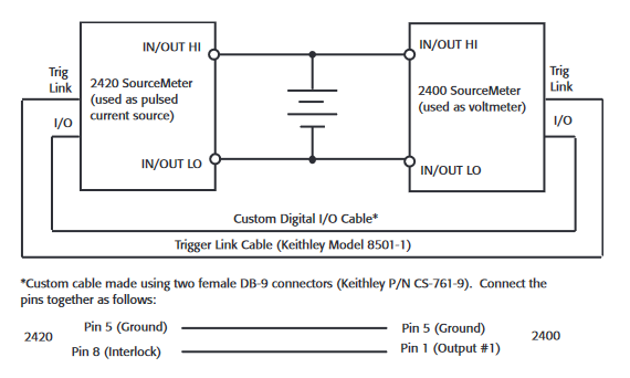
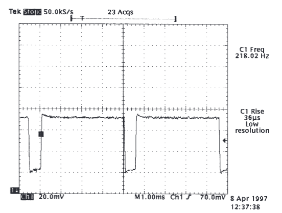
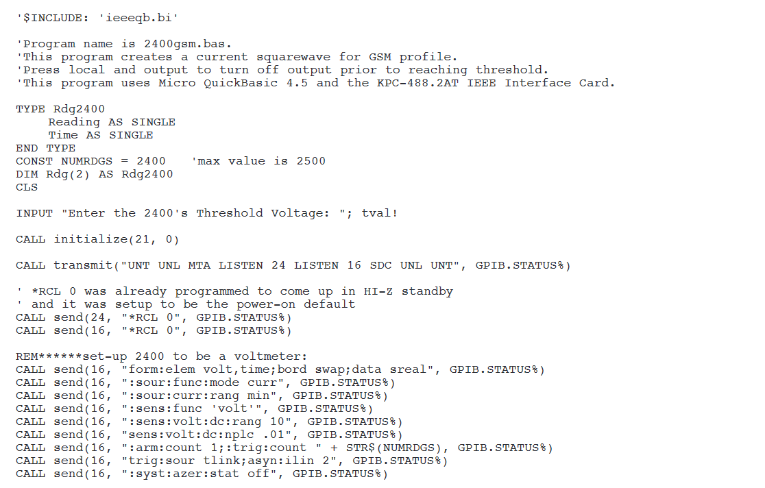
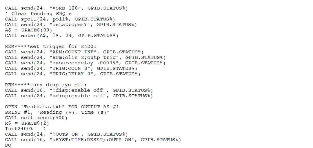
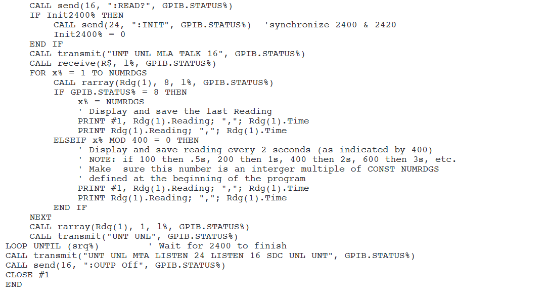
A program (2400GSM.bas) was designed that uses the Model 2420 to create a continuous current waveform of –1.42A for 550µs and –0.224A for 4.1ms. This program is in line with GSM standards. Much as in Example 1, this example also uses the Source List feature to make the pulsed waveform. The waveform repeats until the voltage measured across the battery by the Model 2400 reaches a pre-specified level. The instruments are triggered via their Trigger-Link connectors. The Model 2400 is triggered to measure and compare the voltage during the middle of every –1.42A pulse. However, in order to keep data file sizes manageable, only one reading every two seconds is stored in a data file. Once the Model 2400 reaches the pre-specified voltage limit, it sends a 5V signal via its digital I/O port to the source interlock pin on the digital I/O port of the Model 2420, and the output of this instrument is turned off. An SRQ is generated and the program is stopped.
In order for this program to work properly, the Model 2420 should have Version C09 firmware or later. This firmware enables the trigger model ARM:COUNT to be INFINITE, so the timing of the pulses can be much faster. However, the number of ways to turn off the output becomes limited. In this program, the output of the Model 2420 is turned off after the Model 2400 sends a signal via the digital I/O port to the safety interlock pin on the Model 2420’s digital I/O port. Other ways of turning off the output include pressing OUTPUT on the front panel, sending ABORT or device clear and then output off, and sending *RST or *RCL.
Figure 6 shows the actual output from the Model 2420 as displayed on an oscilloscope with a clamp-on current probe.
IMPORTANT NOTE: Before running this program, both the Model 2400 and Model 2420 must be turned on and then the output of each of these instruments must be set to the high impedance (HI-Z) mode. This is described in the IMPORTANT NOTE at the end of the section titled "Automating the Discharge Cycle."

Testing Multiple Batteries
Because charging/discharging a battery often takes several hours, it may be desirable to connect several batteries in series in order to test them simultaneously. Figure 7 shows the input/output of a single SourceMeter unit connected to 40 batteries in series.

To monitor the individual battery voltages, a separate voltmeter is used through a switch to measure each battery. In this application, the SourceMeter instrument cannot be used as a separate current source and voltmeter because it is limited to a 5V difference between the input/output HI and sense HI terminals.
In this particular example, the SourceMeter instrument is supplying ±10mA to all 40 cells simultaneously so that all the cells can be either charged or discharged at the same time. The total voltage drop of all the batteries is 48 volts, so the Model 2700/7702 is used to measure the voltage of each cell individually. The measured voltage will be compared to a predetermined value in the computer program to determine if it has reached its final voltage value. Since the SourceMeter instrument, switch mainframe, and DMM all have built-in IEEE interfaces, the setup can be automated using a personal computer with an IEEE-488 interface.
To avoid damage to the relays, it is important to synchronize the switch/measure sequence. In particular, before closing a particular channel, make certain all other channels are open. Inadvertently closing multiple channels will short the batteries and may damage the relays. Adding a current limiting resistor or fuse in series with each switch is suggested to help guard against this type of damage.
Alternative Solutions
If current higher than 3A is required to charge or discharge a batter, then the Model 2440 5A SourceMeter unit (5A, 50W source or sink capability) may be used.
If a separate electronic load is used, it may only be necessary to measure the voltage drop across the battery. If this is the case, then a DMM or a switch/measure system can be used to make these measurements. All Keithley Series 2000 DMMs offer DC voltage measurements with high input impedance and a standard IEEE interface. The Model 2700,2701 and 2750 offer the same DMM features, plus a built-in 2-slot or 5-slot switch mainframe.
Find more valuable resources at TEK.COM
Copyright © Tektronix. All rights reserved. Tektronix products are covered by U.S. and foreign patents, issued and pending. Information in this publication supersedes that in all previously published material. Specification and price change privileges reserved. TEKTRONIX and TEK are registered trademarks of Tektronix, Inc. All other trade names referenced are the service marks, trademarks or registered trademarks of their respective companies.
No. 1946 02041KGW