SDH Frame Structure
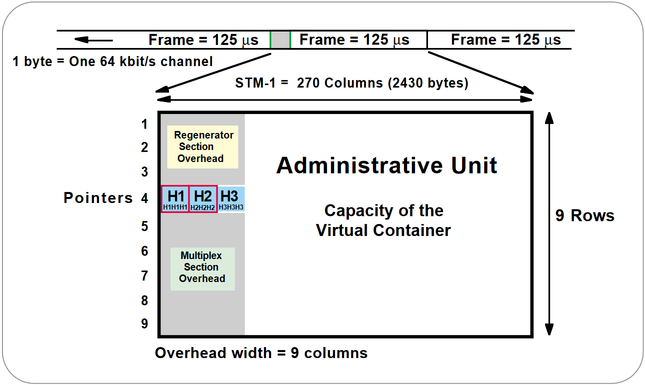
The STM-1 frame is the basic transmission format for SDH. The frame lasts for 125 microseconds, therefore, there are 8000 frames per second.
The STM-1 frame consists of overhead plus a virtual container capacity (see Figure 1). The first nine columns of each frame make up the Section Overhead, and the last 261 columns make up the Virtual Container (VC) capacity. The VC plus the pointers (H1, H2, H3 bytes) is called the AU (Administrative Unit).
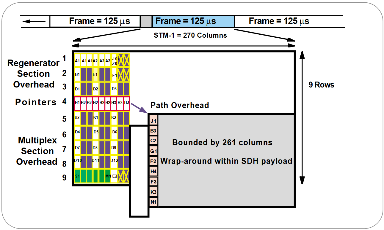
Carried within the VC capacity, which has its own frame structure of nine rows and 261 columns, is the Path Overhead and the Container (see Figure 2). The first column is for Path Overhead; it’s followed by the payload container, which can itself carry other containers.
Virtual Containers can have any phase alignment within the Administrative Unit, and this alignment is indicated by the Pointer in row four, as described later in the Pointers section. Within the Section Overhead, the first three rows are used for the Regenerator Section Overhead, and the last five rows are used for the Multiplex Section Overhead.
The STM frame is transmitted in a byte-serial fashion, row-by-row, and is scrambled immediately prior to transmission to ensure adequate clock timing content for downstream regenerators.
Virtual Container
SDH supports a concept called virtual containers (VC). Through the use of pointers and offset values, VCs can be carried in the SDH payload as independent data packages. VCs are used to transport lower-speed tributary signals. Figure 2 illustrates the location of a VC-4 within the STM1 frame. Note that it can start (indicated by the J1 path overhead byte) at any point within the STM-1 frame. The start location of the J1 byte is indicated by the pointer byte values.
Virtual containers can also be concatenated to provide more capacity in a flexible fashion.
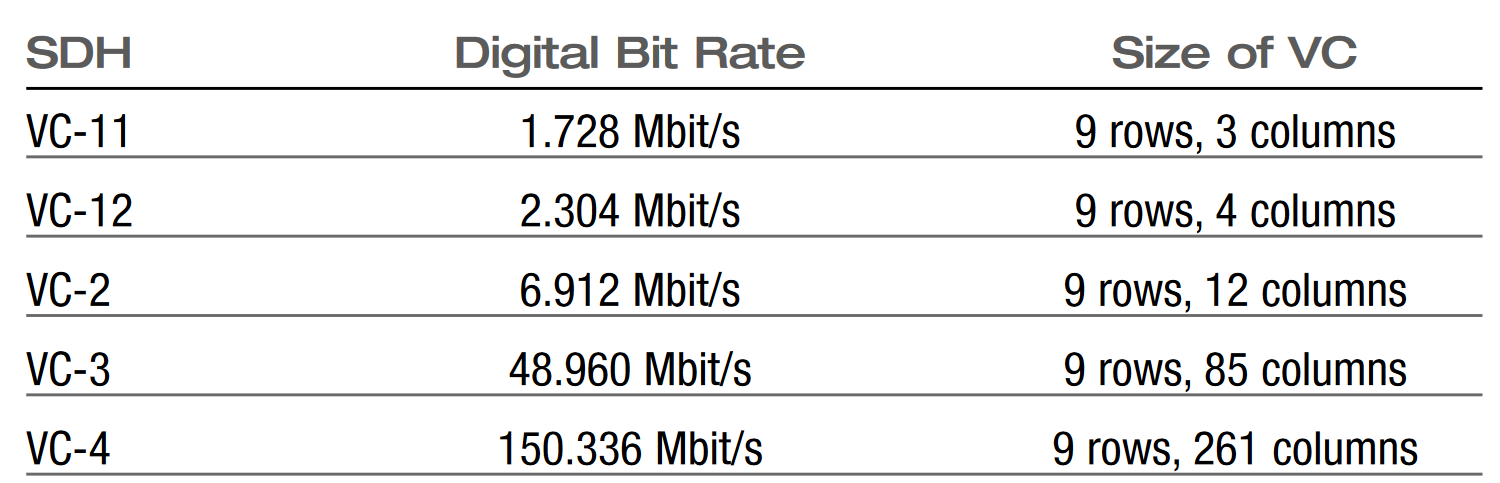
Table 1 lists the names and some of the parameters of the virtual containers.
Table 1. Virtual Containers (VC)
SDH Overhead
The SDH standard was developed using a client/server layer approach (see Figure 3). The overhead and transport functions are divided into layers. They are:
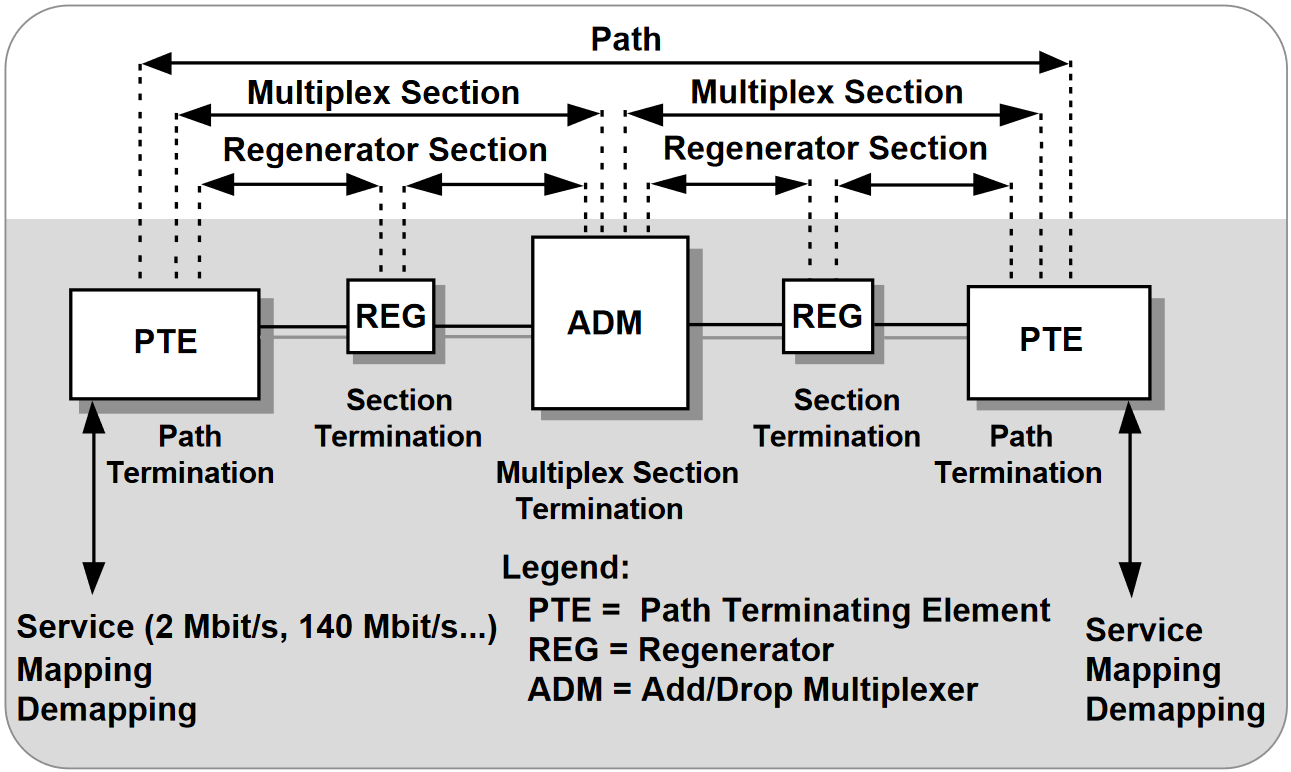
- Regenerator Section
- Multiplex Section
- Path
The layers have a hierarchical relationship, with each layer building on the services provided by all the lower layers.
This section details the different SDH overhead information, specifically:
- Regenerator Section
- Multiplex Section
- Path Overhead
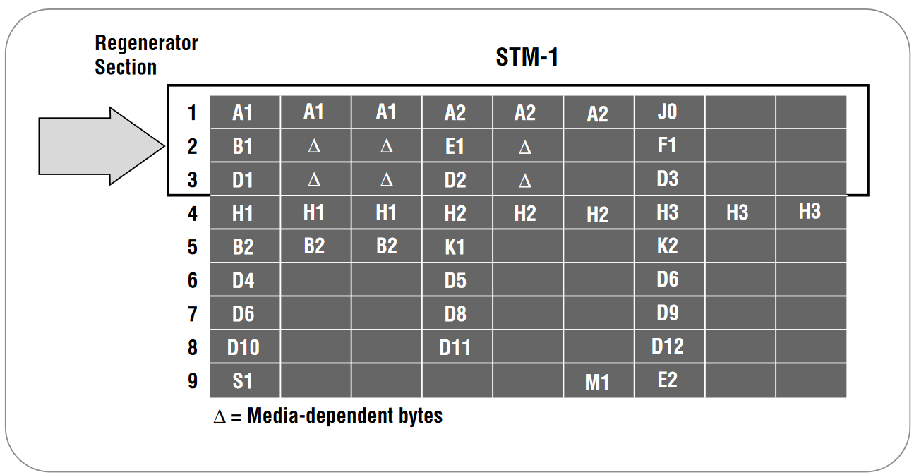
Regenerator Section Overhead
The Regenerator Section Overhead contains only the information required for the elements located at both ends of a section. This might be two regenerators, a piece of line terminating equipment and a regenerator, or two pieces of line terminating equipment.
The Regenerator Section Overhead is found in the first three rows of Columns 1 through 9 of the STM-1 frame (see Figure 4). Byte by byte, the Regenerator Section Overhead is shown in Table 4.
Multiplex Section Overhead
The Multiplex Section Overhead contains the information required between the multiplex section termination equipment at each end of the Multiplex section (that is, between consecutive network elements excluding the regenerators).
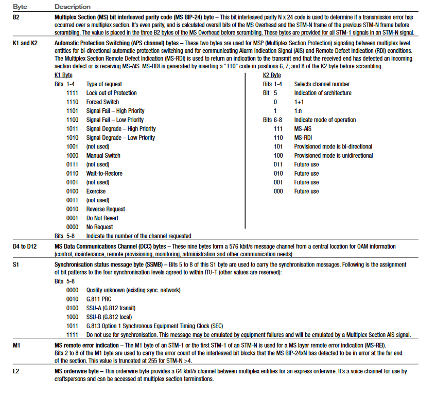
The Multiplex Section Overhead is found in Rows 5 to 9 of Columns 1 through 9 of the STM-1 frame (see Figure 5). Byte by byte, the Multiplex Section Overhead is shown in Table 5.
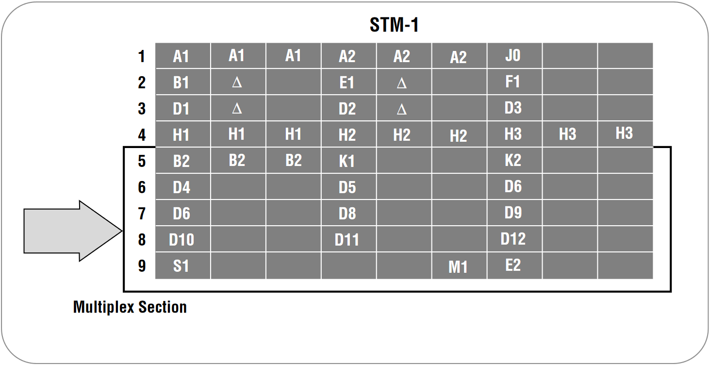
Table 2. Regenerator Section Overhead
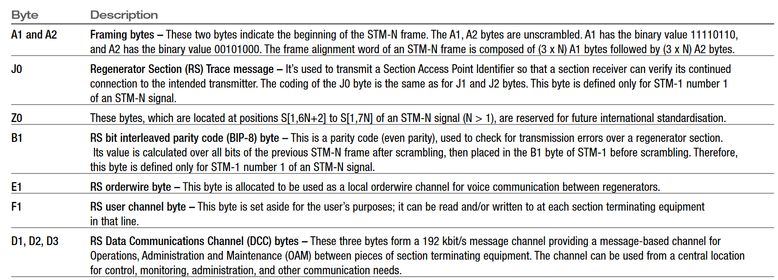
Table 3. Multiplex Section Overhead
Higher-Order Path Overhead (VC-4/VC-3)
The Path Overhead is assigned to, and transported with the Virtual Container from the time it’s created by path terminating equipment until the payload is demultiplexed at the termination point in a piece of path terminating equipment.
The Path Overhead is found in Rows 1 to 9 of the first column of the VC-4 or VC-3 (see Figure 6). Byte by byte, the Higher Order Path Overhead is shown in Table 6.
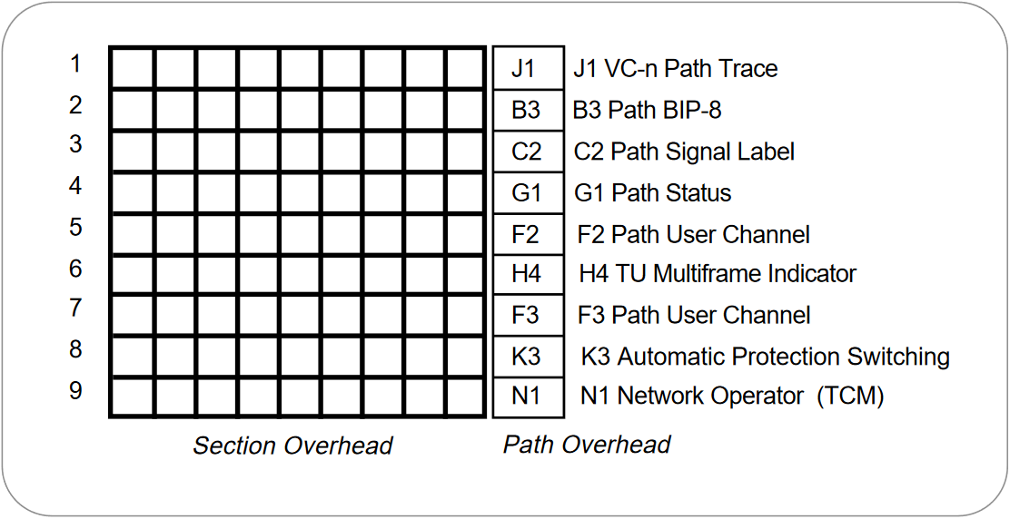
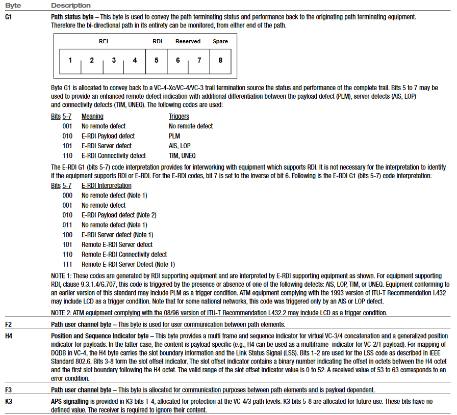
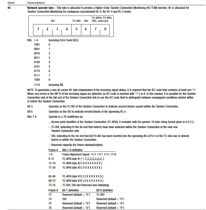
Table 4. Higher-Order Path Overhead
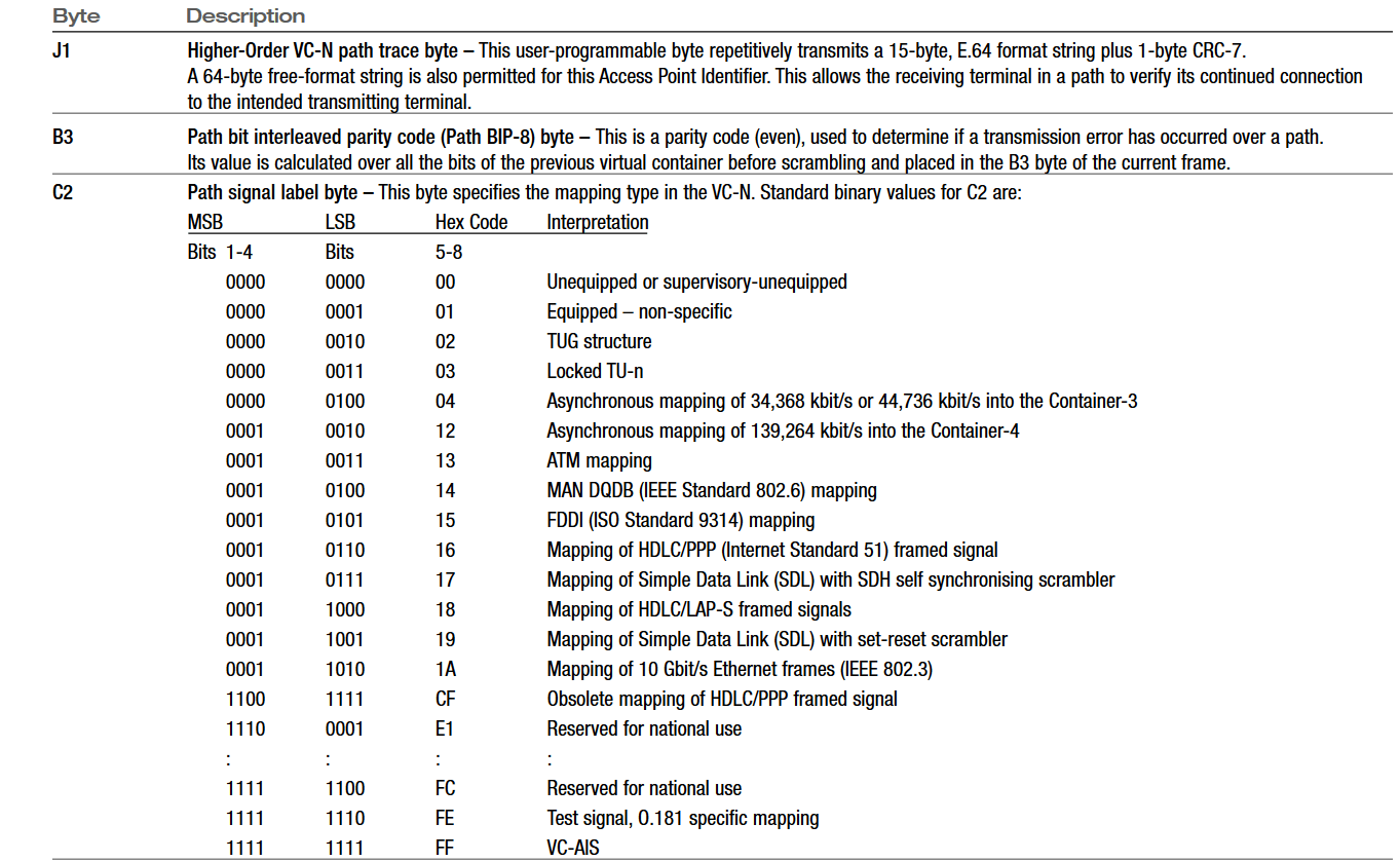
Table 4 (contd)
Find more valuable resources at TEK.COM
Copyright © Tektronix. All rights reserved. Tektronix products are covered by U.S. and foreign patents, issued and pending. Information in this publication supersedes that in all previously published material. Specification and price change privileges reserved. TEKTRONIX and TEK are registered trademarks of Tektronix, Inc. All other trade names referenced are the service marks, trademarks or registered trademarks of their respective companies.
8/01 2RX-11694-2