Jerry Janesch Keithley Instruments, Inc.
Most precision digital multimeters (DMMs) and many Source Measurement Units (SMUs) offer both two-wire and four-wire resistance measurement capabilities. However, these two techniques are not equally well suited for all resistance measurement applications.This article offers a quick overview of how to determine the most appropriate technique for a specific application.
DMMs typically employ the constantcurrent method to measure resistance, which sources a constant current (ISOUR) to the device under test (DUT) and measures the voltage (VMEAS). Resistance (RDUT) is then calculated and displayed using the known current and measured voltage (RDUT = VMEAS/ISOUR). Figure 1 shows a simple diagram of the constant-current test
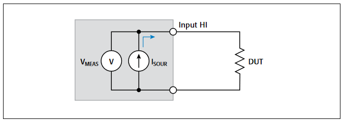
Table 1. Typical DMM ranges and test currents
| Measurement Range | Test Current |
| 100 Ω | 1 mA |
| 1 kΩ | 1 mA |
| 10 kΩ | 100 μA |
| 100 kΩ | 10 μA |
| 1 MΩ | 1 μA |
| 10 MΩ | 0.1 μA |
| 100 MΩ | 0.1 μA |
Two-Wire Resistance Measurements
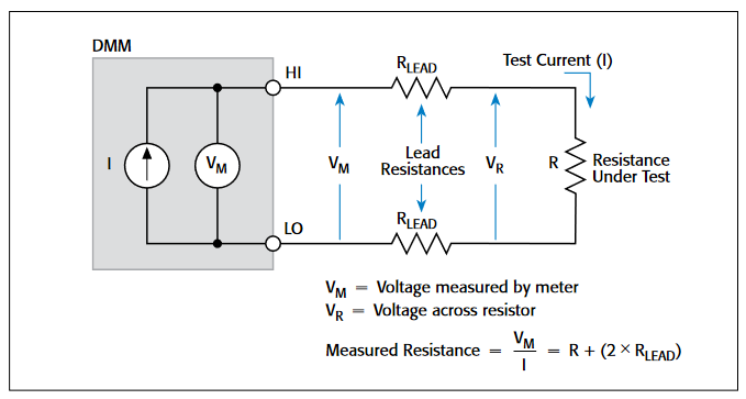
Figure 2 represents a two-wire resistance test configuration employing the constant current method.
The main measurement issue with the two-wire method, as applied to low resistance measurements, is that the total lead resistance (RLEAD) is added to the measurement. Because the test current (I) causes a small but significant voltage drop across the lead resistances, the voltage (VM) measured by the meter won't be exactly the same as the voltage (VR) directly across the test resistance (R), and considerable error can result.Typical lead resistances range from 10mΩ to 1Ω, so it's very difficult to obtain accurate two-wire resistance measurements when the resistance under test is lower than 100Ω because the resistance of interest will be completely swamped by the lead resistance.In fact, lead resistance will be the dominant source of error. For example, using test leads with a 100mΩ combined resistance to perform a two-wire resistance measurement on a 500mΩ resistor will result in a 20% measurement error in addition to that of the instrument.
Four-Wire (Kelvin) Resistance Measurements
Due to the limitations of the two-wire method, a different approach is used for low resistance measurements that reduce the effect of test lead resistance. For measuring DUTs with resistances equal to or less than 1kΩ, test engineers may use the four-wire (Kelvin) connection shown in Figure 3.Because the voltage is measured at the DUT, voltage drop in the test leads is eliminated (this voltage could be significant when measuring low-resistance devices).
With this configuration, the test current (I) is forced through the test resistance (R) via one set of test leads, while the voltage (VM) across the DUT is measured through a second set of leads (sense leads).
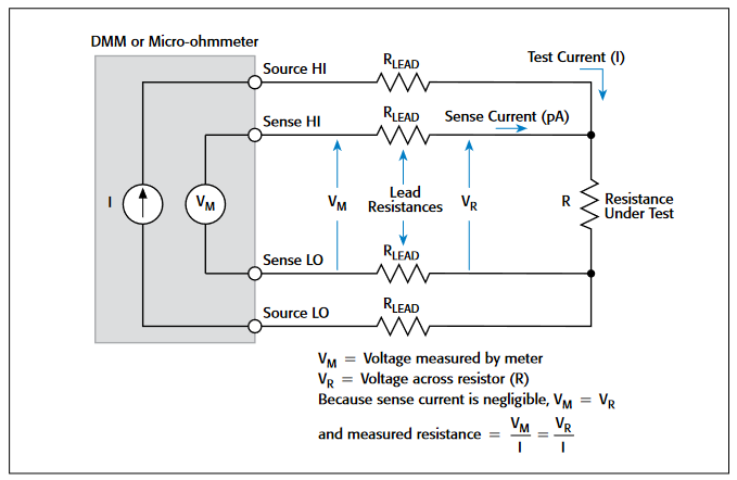
Although some small current (typically less than 100pA) may flow through the sense leads, it is usually negligible and can generally be ignored for all practical purposes.Therefore the voltage measured by the meter (VM) is essentially the same as the voltage (VR) across the resistance (R). As a result, the resistance value can be determined much more accurately than with the two-wire method. Note that the voltage-sensing leads should be connected as close to the resistor under test as possible to avoid including part of the resistance of the test leads in the measurement.

Find more valuable resources at TEK.COM
Copyright © Tektronix. All rights reserved. Tektronix products are covered by U.S. and foreign patents, issued and pending. Information in this publication supersedes that in all previously published material. Specification and price change privileges reserved. TEKTRONIX and TEK are registered trademarks of Tektronix, Inc. All other trade names referenced are the service marks, trademarks or registered trademarks of their respective companies.
No.3226 05.09.13