联系我们
与泰克代表实时聊天。 工作时间:上午 9:00 - 下午 5:00(太平洋标准时间)。
致电我们
工作时间:上午9:00-下午5:00(太平洋标准时间)
下载
下载手册、产品技术资料、软件等:
反馈
THDP0100/0200 and TMDP0200 User Manual
This document contains instructions for using the probes and accessories, and includes performance verification procedures.
此手册适用于:
THDP0100, THDP0200, TMDP0200
By downloading, you agree to the terms and conditions of the Manuals Download Agreement.
Manuals Download Agreement
ATTENTION: please read the following terms and conditions carefully before downloading any documents from this website. By downloading manuals from Tektronix' website, you agree to the following terms and conditions:
Manuals for Products That Are Currently Supported:
Tektronix hereby grants permission and license to owners of Tektronix instruments to download and reproduce the manuals on this website for their own internal or personal use. Manuals for currently supported products may not be reproduced for distribution to others unless specifically authorized in writing by Tektronix, Inc.
A Tektronix manual may have been revised to reflect changes made to the product during its manufacturing life. Thus, different versions of a manual may exist for any given product. Care should be taken to ensure that one obtains the proper manual version for a specific product serial number.
Manuals for Products That Are No Longer Supported:
Tektronix cannot provide manuals for measurement products that are no longer eligible for long term support. Tektronix hereby grants permission and license for others to reproduce and distribute copies of any Tektronix measurement product manual, including user manuals, operator's manuals, service manuals, and the like, that (a) have a Tektronix Part Number and (b) are for a measurement product that is no longer supported by Tektronix.
A Tektronix manual may be revised to reflect changes made to the product during its manufacturing life. Thus, different versions of a manual may exist for any given product. Care should be taken to ensure that one obtains the proper manual version for a specific product serial number.
This permission and license does not apply to any manual or other publication that is still available from Tektronix, or to any manual or other publication for a video production product or a color printer product.
Disclaimer:
Tektronix does not warrant the accuracy or completeness of the information, text, graphics, schematics, parts lists, or other material contained within any measurement product manual or other publication that is not supplied by Tektronix or that is produced or distributed in accordance with the permission and license set forth above.
Tektronix may make changes to the content of this website or to its products at any time without notice.
Limitation of Liability:
TEKTRONIX SHALL NOT BE LIABLE FOR ANY DAMAGES WHATSOEVER (INCLUDING, WITHOUT LIMITATION, ANY CONSEQUENTIAL OR INCIDENTAL DAMAGES, DAMAGES FOR LOSS OF PROFITS, BUSINESS INTERRUPTION, OR FOR INFRINGEMENT OF INTELLECTUAL PROPERTY) ARISING OUT OF THE USE OF ANY MEASUREMENT PRODUCT MANUAL OR OTHER PUBLICATION PRODUCED OR DISTRIBUTED IN ACCORDANCE WITH THE PERMISSION AND LICENSE SET FORTH ABOVE.
Read Online
Important safety information
This manual contains information and warnings that must be followed by the user for safe operation and to keep the product in a safe condition.
To safely perform service on this product, see the Service safety summary that follows the General safety summary.
General safety summary
Use the product only as specified. Review the following safety precautions to avoid injury and prevent damage to this product or any products connected to it. Carefully read all instructions. Retain these instructions for future reference.
This product shall be used in accordance with local and national codes.
For correct and safe operation of the product, it is essential that you follow generally accepted safety procedures in addition to the safety precautions specified in this manual.
The product is designed to be used by trained personnel only.
Only qualified personnel who are aware of the hazards involved should remove the cover for repair, maintenance, or adjustment.
Before use, always check the product with a known source to be sure it is operating correctly.
This product is not intended for detection of hazardous voltages.
Use personal protective equipment to prevent shock and arc blast injury where hazardous live conductors are exposed.
While using this product, you may need to access other parts of a larger system. Read the safety sections of the other component manuals for warnings and cautions related to operating the system.
When incorporating this equipment into a system, the safety of that system is the responsibility of the assembler of the system.
To avoid fire or personal injury
Connect and disconnect properly
Do not connect or disconnect probes or test leads while they are connected to a voltage source.
Use only insulated voltage probes, test leads, and adapters supplied with the product, or indicated by Tektronix to be suitable for the product.
Observe all terminal ratings
To avoid fire or shock hazard, observe all rating and markings on the product. Consult the product manual for further ratings information before making connections to the product.
Do not exceed the Measurement Category (CAT) rating and voltage or current rating of the lowest rated individual component of a product, probe, or accessory. Use caution when using 1:1 test leads because the probe tip voltage is directly transmitted to the product.
Do not apply a potential to any terminal, including the common terminal, that exceeds the maximum rating of that terminal.
Do not operate without covers
Do not operate this product with covers or panels removed, or with the case open. Hazardous voltage exposure is possible.
Avoid exposed circuitry
Do not touch exposed connections and components when power is present.
Do not operate with suspected failures
If you suspect that there is damage to this product, have it inspected by qualified service personnel.
Disable the product if it is damaged. Do not use the product if it is damaged or operates incorrectly. If in doubt about safety of the product, turn it off and disconnect the power cord. Clearly mark the product to prevent its further operation.
Before use, inspect voltage probes, test leads, and accessories for mechanical damage and replace when damaged. Do not use probes or test leads if they are damaged, if there is exposed metal, or if a wear indicator shows.
Examine the exterior of the product before you use it. Look for cracks or missing pieces.
Use only specified replacement parts.
Do not operate in wet/damp conditions
Be aware that condensation may occur if a unit is moved from a cold to a warm environment.
Do not operate in an explosive atmosphere
Keep product surfaces clean and dry
Remove the input signals before you clean the product.
Probes and test leads
Before connecting probes or test leads, connect the power cord from the power connector to a properly grounded power outlet.
Keep fingers behind the protective barrier, protective finger guard, or tactile indicator on the probes. Remove all probes, test leads and accessories that are not in use.
Use only correct Measurement Category (CAT), voltage, temperature, altitude, and amperage rated probes, test leads, and adapters for any measurement.
Beware of high voltages
Understand the voltage ratings for the probe you are using and do not exceed those ratings. It is important to know and understand he maximum measurement voltage from the probe tip to the probe reference lead.
The voltage rating depends on the probe and your application. Refer to the Specifications section of the manual for more information.
 | WARNING:To prevent electrical shock, do not exceed the maximum measurement or maximum floating voltage for the oscilloscope input BNC connector, probe tip, or probe reference lead. |
| WARNING:To prevent damage to the alligator clip insulation, do not use in high A/m magnetic fields at high frequencies, which can cause induction heating of the jaws. |
Connect and disconnect properly.
Connect the probe output to the measurement product before connecting the probe to the circuit under test. Connect the probe reference lead to the circuit under test before connecting the probe input. Disconnect the probe input and the probe reference lead from the circuit under test before disconnecting the probe from the measurement product.
Inspect the probe and accessories
Before each use, inspect probe and accessories for damage (cuts, tears, or defects in the probe body, accessories, or cable jacket). Do not use if damaged.
Service safety summary
The Service safety summary section contains additional information required to safely perform service on the product. Only qualified personnel should perform service procedures. Read this Service safety summary and the General safety summary before performing any service procedures.
To avoid electric shock
Do not touch exposed connections.
Do not service alone
Do not perform internal service or adjustments of this product unless another person capable of rendering first aid and resuscitation is present.
Disconnect power
To avoid electric shock, switch off the product power and disconnect the power cord from the mains power before removing any covers or panels, or opening the case for servicing.
Use care when servicing with power on
Dangerous voltages or currents may exist in this product. Disconnect power, remove battery (if applicable), and disconnect test leads before removing protective panels, soldering, or replacing components.
Verify safety after repair
Always recheck ground continuity and mains dielectric strength after performing a repair.
Terms in this manual
These terms may appear in this manual:
| WARNING:Warning statements identify conditions or practices that could result in injury or loss of life. |
| CAUTION:Caution statements identify conditions or practices that could result in damage to this product or other property. |
Terms on the product
These terms may appear on the product:
- DANGER indicates an injury hazard immediately accessible as you read the marking.
- WARNING indicates an injury hazard not immediately accessible as you read the marking.
- CAUTION indicates a hazard to property including the product.
Symbols on the product
 | When this symbol is marked on the product, be sure to consult the manual to find out the nature of the potential hazards and any actions which have to be taken to avoid them. (This symbol may also be used to refer the user to ratings in the manual.) |
The following symbols(s) may appear on the product.
 CAUTION: Refer to Manual |  Earth Terminal | 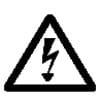 WARNING: High Voltage |
Compliance information
This section lists the safety and environmental standards with which the instrument complies. This product is intended for use by professionals and trained personnel only; it is not designed for use in households or by children.
Compliance questions may be directed to the following address:
Tektronix, Inc.
PO Box 500, MS 19-045
Beaverton, OR 97077, USA
Safety compliance
This section lists the safety standards with which the product complies and other safety compliance information.
EU declaration of conformity – low voltage
Compliance was demonstrated to the following specification as listed in the Official Journal of the European Union:
Low Voltage Directive 2014/35/EU.
- EN 61010-031. Particular requirements for handheld probe assemblies for electrical measurement and test equipment
U.S. nationally recognized testing laboratory listing
- UL 61010-031. Particular requirements for handheld probe assemblies for electrical measurement and test equipment
Canadian certification
- CAN/CSA-C22.2 No. 61010-031. Particular requirements for handheld probe assemblies for electrical measurement and test equipment
Additional compliances
- IEC 61010-031. Particular requirements for handheld probe assemblies for electrical measurement and test equipment
Equipment type
Test and measuring equipment.
Pollution degree rating
Pollution degree 2 (as defined in IEC 61010-1). Rated for indoor, dry location use only.
IP rating
IP20 (as defined in IEC 60529).
Measurement and overvoltage category descriptions
Measurement terminals on this product may be rated for measuring mains voltages from one or more of the following categories (see specific ratings marked on the product and in the manual).
- Overvoltage Category I. For equipment intended to be connected to a mains supply in which means have been taken to substantially and reliably reduce transient overvoltages to a level where they cannot cause a hazard.
- Measurement Category II. For measurements performed on circuits directly connected to the low-voltage installation.
- Measurement Category III. For measurements performed in the building installation.
- Measurement Category IV. For measurements performed at the source of low-voltage installation.
| Note:Only mains power supply circuits have an overvoltage category rating. Only
measurement circuits have a measurement category rating. Other circuits within the
product do not have either rating. |
Mains overvoltage category rating
Overvoltage category II (as defined in IEC 61010-1).
Environmental compliance
This section provides information about the environmental impact of the product.
Product end-of-life handling
Observe the following guidelines when recycling an instrument or component:
- Equipment recycling
- Production of this equipment required the extraction and use of natural resources. The equipment may contain substances that could be harmful to the environment or human health if improperly handled at the product’s end of life. To avoid release of such substances into the environment and to reduce the use of natural resources, we encourage you to recycle this product in an appropriate system that will ensure that most of the materials are reused or recycled appropriately.
 |
This symbol indicates that this product complies with the applicable European Union requirements according to Directives 2012/19/EU and 2006/66/EC on waste electrical and electronic equipment (WEEE) and batteries. For information about recycling options, check the Tektronix Web site (http://www.tek.com/productrecycling). |
Overview
This document provides operating information and specifications for the Tektronix THDP0100/0200 and TMDP0200 high voltage differential probes. The probes share similar functions, properties, and operating procedures, and are discussed first, followed by the specifications, which differ by probe model. Service procedures include performance verification and adjustments.
| WARNING:Only use the accessories that are designed for your probe and that are rated at or above the voltages you are measuring. |
| Name | Bandwidth | Peak voltage range | Oscilloscope interface |
|---|---|---|---|
| THDP0100 | 100 MHz | 600 V/6000 V | TekVPI |
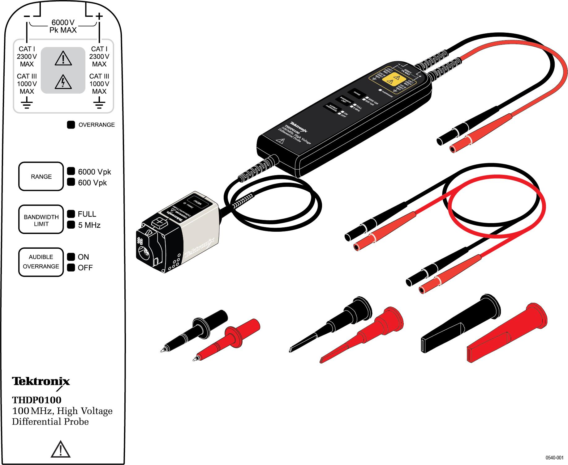
| THDP0200 | 200 MHz | 150 V/1500 V | TekVPI |
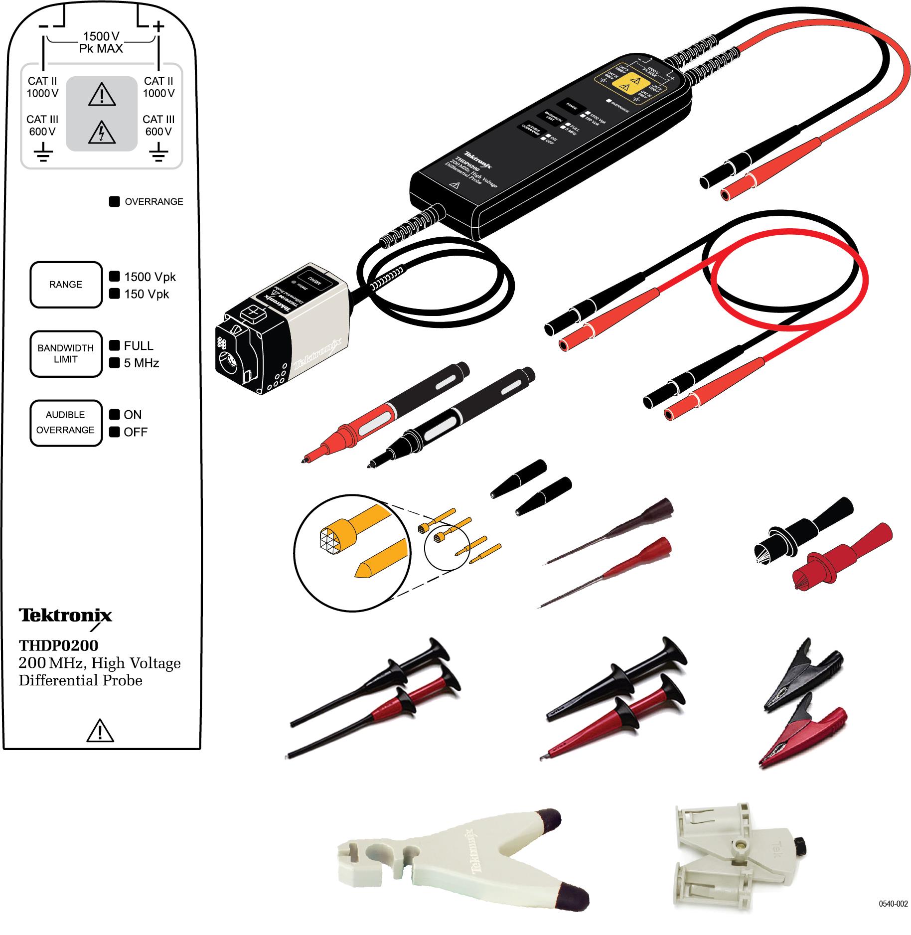
| TMDP0200 | 200 MHz | 75 V/750 V | TekVPI |
Probe operating information
This section of the manual describes how to make connections to the instrument and to your circuit, followed by descriptions of the probe controls and indicators.
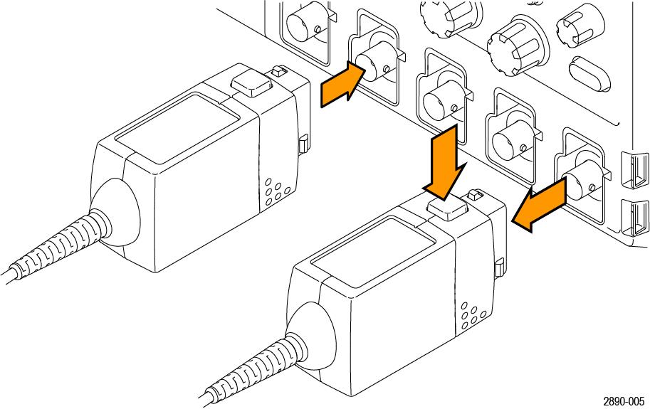
Connecting to the instrument
- Connect the probe to the input of the oscilloscope.
- All of the LEDs on the probe body briefly light, and then indicate the settings from the previous session.
- The Status LED on the probe control box lights amber as the probe completes a self-test.
- The Status LED goes off briefly and then lights green to indicate the probe is ready to use.

- Adjust the vertical offset (or position) of the oscilloscope input.
- Select the proper range setting. For example, when using the THDP0200 probe, to achieve higher resolution and less noise when measuring signals below 150 Vpk, switch the RANGE to 150 V. If the OVERRANGE indicator lights or flashes, the output signal may not be accurate. Use the 1500 V range setting instead.WARNING:To avoid electrical shock, observe proper safety precautions when working with voltages above 60 VDC or 30 VACRMS. These voltage levels pose a shock hazard. Use only the accessories specified with the probe that you are using. Make sure that the accessories are fully mated before connecting or disconnecting.WARNING:To avoid electrical shock or fire, make sure the test leads are in good condition. The input leads and extender leads have a jacket wear indicator which becomes visible if the wire jacket becomes excessively worn. If the wear indicator is visible, do not use the probe. Contact Tektronix Service for repair or replacement.WARNING:To avoid electrical shock or fire, keep the probe body and output cable of the probe away from the circuits being measured. The probe body and output cable are not intended to be in contact with the circuits being measured.
- Use the probe accessories to connect the probe inputs to the circuit points to be measured.
Connecting to the circuit
Make the connections to your circuit using the integral input leads or the accessories that best fit your application. The integral input leads extend 10 in (25 cm) from the probe body. Connect the leads directly to your circuit, or use the extender leads and the accessories that are included with the probe.
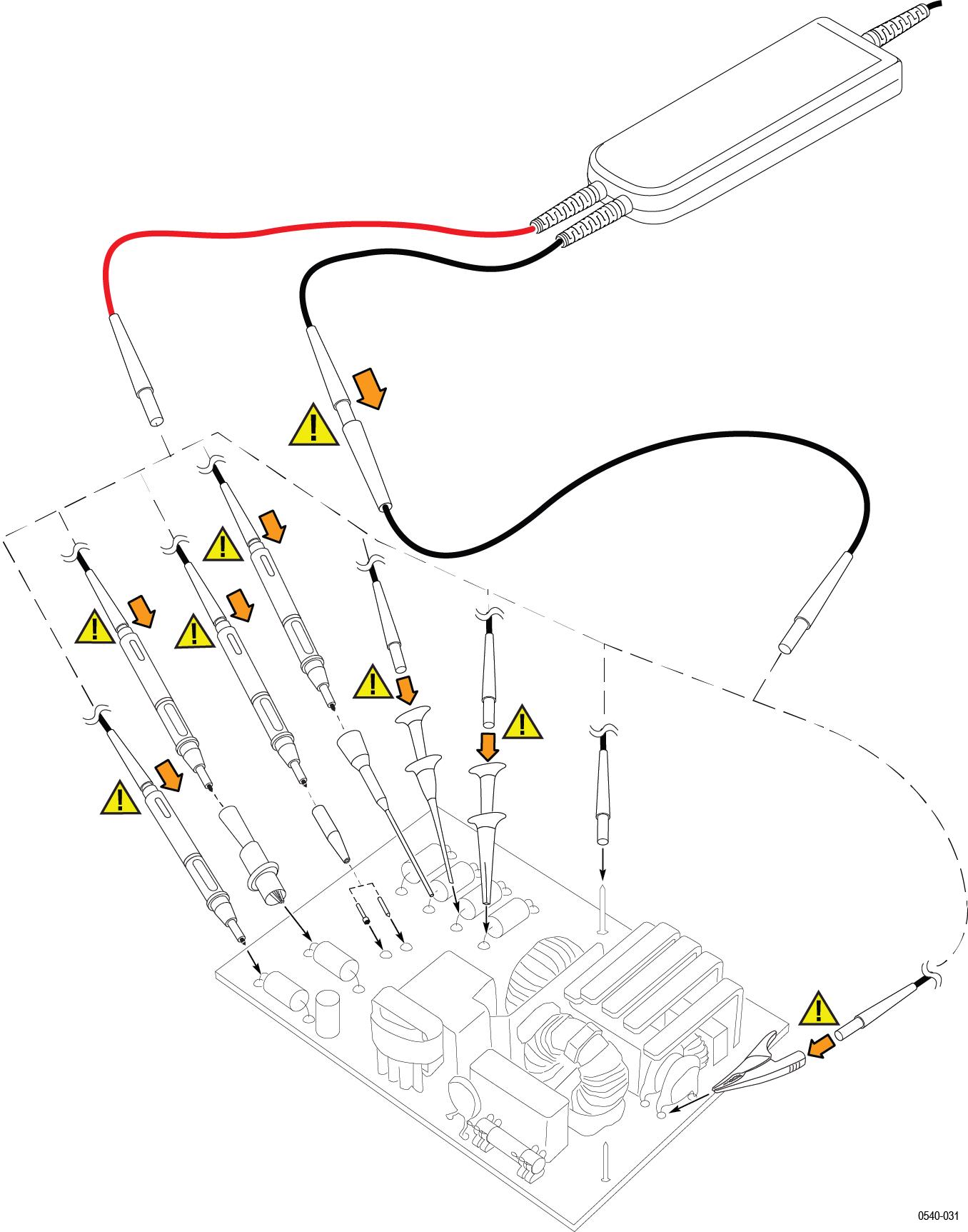
| WARNING:To avoid electrical shock or fire, always make the connections from the test leads to the probe accessory that you intend to use before you make any connections to a voltage source. Always ensure that the connections between the test leads and the probe accessories are secure before you connect them to a voltage source. Do not connect or disconnect accessories or extended test leads to a voltage source unless they are first connected to the probe. |
Probe controls and indicators
The probes have several features that make probing and measurement a simpler task. Familiarize yourself with the controls and indicators shown on the following pages. Some features differ from those illustrated, such as probe input voltage limit and voltage range, depending on the probe model.
The probe release button, Status LED, and MENU buttons are located on the probe control box.
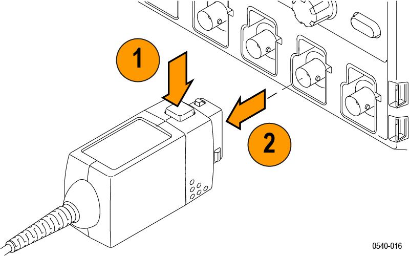
Probe release button
Press the release button to unlatch the probe from the instrument, and then pull the probe straight out.
| WARNING:To avoid electrical shock, disconnect the probe inputs from the circuit before disconnecting the probe from the instrument. |
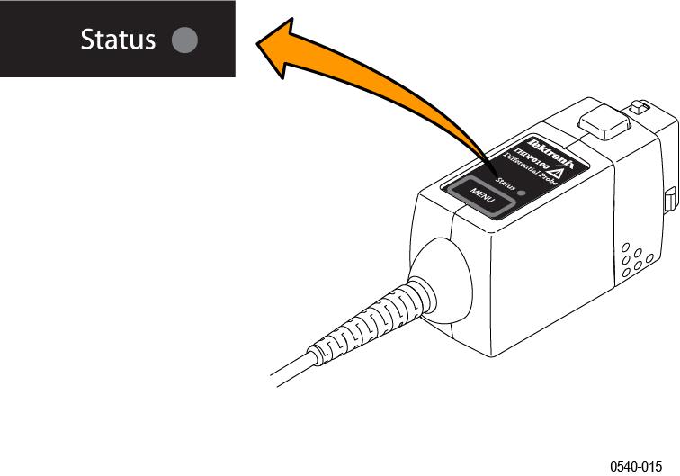
Status LED
When the probe is connected to the instrument, the Status LED lights amber as the probe completes a self-test. Then, the Status LED goes off briefly and then lights green to indicate the probe is ready to use.
The Status LED lights amber or red if the power-on test failed, or any time an error occurs. If the Status LED light does not light green after the self-test, first disconnect the probe from the circuit under test, and then disconnect the probe from the oscilloscope.
Reconnect the probe to the oscilloscope and check that the Status LED lights amber, and then green. If the Status LED continues to light amber or red, there may be other remedies. See Error conditions.
Menu button
Press the MENU button to display on-screen probe controls on the oscilloscope. Many probe functions are available, such as AutoZero and range selection.
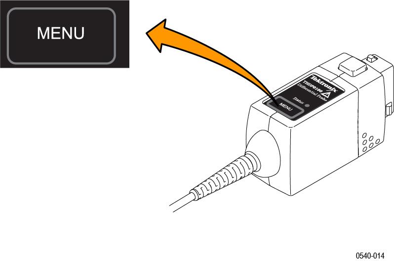
The remaining controls and features of the probe are located on the probe head.
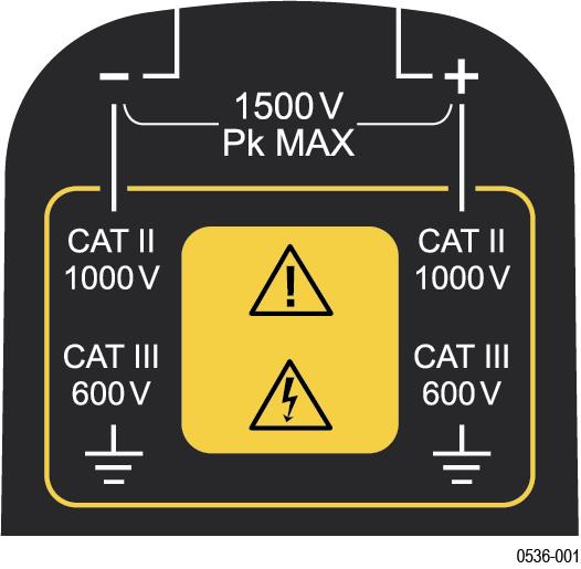
Probe inputs
The maximum voltage that the probe inputs can accept depend on the probe model and the measurement points.
For example, the THDP0200 probe (shown) can measure a maximum of 1,000 VRMS CAT II between either input and ground, and a maximum difference of 1,500 V (DC + peak AC) between the (–) and (+) inputs. These input ratings are valid for both range settings.
The other probes covered in this manual have different limits; refer to Specifications.
| CAUTION:Do not use these probes above the input limits shown on the probes. The input voltage limits vary by probe model. |
Overrange indicator
The OVERRANGE indicator lights red if the voltage of the input differential signal exceeds the linear range of the range setting. When this happens, the signal on the probe output does not accurately represent the signal on the probe input.
| WARNING:The Overrange indicator does not detect overrange condition of common-mode voltages or voltage-to-earth potential at the probe inputs. The Overrange indicator only detects differentially between the + and – inputs (not relative to ground). Do not exceed the common-mode voltage or input voltage-to-earth ratings of the probe when taking measurements. See Overrange detection. If you are not sure, make a single-ended measurement of each point you are intending to measure differentially first. Make a single-ended measurement by tying one input lead to ground (the "–" input) and then connecting the other lead (the “+" input) to the points of interest, one at a time. |

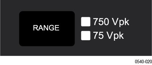
Voltage range button and indicators
Press the RANGE button to select between the voltage range (attenuation) settings of the probe. The voltage range is indicated by two LEDs on the probe and may be displayed on the oscilloscope screen, depending on the oscilloscope model.
The OVERRANGE LED lights if the applied voltage exceeds the selected range. To extinguish the LED, select a higher range. If a higher range is not available, do not attempt to take the measurement with the probe.
Bandwidth limit button and indicators
Press the BANDWIDTH LIMIT button to limit the probe bandwidth to 5 MHz. 5 MHz is close to the switching frequency of most switching transistors (FETs) in switch mode power supplies (SMPS).
The 5 MHz filter assists in the characterization and testing of power supplies in switch mode by removing all high frequency content, noise and harmonics from the measurement.
Press the button again to return to the FULL position, which selects the full specified bandwidth of the probe.

Audible overrange on/off button and indicators
The audible overrange is an audible alarm that indicates when the measured signal exceeds the selected range. The alarm is enabled when the probe is first powered on.
Press the AUDIBLE OVERRANGE button to light the OFF LED and disable the feature. To enable the alarm, press the button again to light the ON LED.

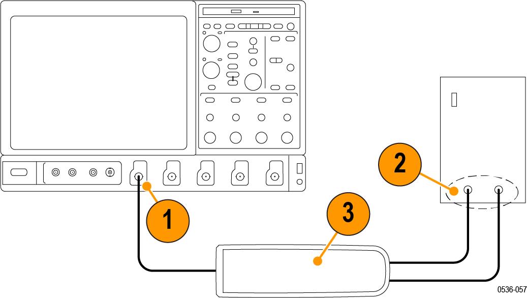
Functional check
Using accessories that are shipped with your probe and a source that supplies AC line voltage, perform the following procedure:
| WARNING:To reduce risk of shock or fire, ensure that the accessories are fully mated before you connect to voltage sources above 42 Vpk. |
- Connect the output of the probe to the oscilloscope input channel.
- Connect the probe inputs to the AC voltage source.
- Connect the inputs, set the voltage range, and perform the check as each row of the following table indicates.
| Input 1 (+ or –) | Input 2 (– or +) | Mode | Range setting | Check |
|---|---|---|---|---|
| Hot | Ground or Neutral | Differential | High (6000 V, 1500 V, or 750 V) | Measurement instrument displays or indicates the line voltage |
| Hot | Ground or Neutral | Differential | Low (600 V, 150 V, or 75 V) | Measurement instrument displays or indicates the line voltage. Overrange indicator lights if the input is ~20% over |
| Hot | Hot (same connection) | Common Mode | High or low |
No signal. If a DC offset voltage is present, zero the DC offset using the AutoZero function. |
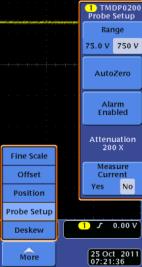
AutoZero
The host instrument includes a feature that nulls the DC offset at the output of the probe. To initiate the AutoZero routine, do the following:
- Allow the probe and oscilloscope to warm up for 20 minutes.
- Press the MENU button on the probe to display the Probe Setup screen on the oscilloscope.
Figure 1. Probe Setup screen - Connect the probe inputs together with the hook tips.
- Press AutoZero on the Probe Setup screen to initiate the AutoZero routine. If the AutoZero routine does not yield sufficient results, use the DC Offset Zero procedure.
DC offset zero
The offset stored through this feature is retained in the probe between probe power cycles. To set the probe DC offset to 0 V, do the following:
- Set the oscilloscope offset for the probe channel to 0 volts.
- Connect the probe inputs together with the hook tips.
- Press and hold the probe BANDWIDTH LIMIT and RANGE buttons until the OVERRANGE LED on the probe begins flashing, and then quickly release the buttons (about 2 seconds).
-
Use the probe BANDWIDTH LIMIT or RANGE buttons to set the probe offset voltage to 0 V, as displayed on the oscilloscope. The BANDWIDTH LIMIT button decreases the offset voltage and the RANGE button increases it.
- Press the AUDIBLE OVERRANGE button on the probe to store the value. The OVERRANGE LED on the probe stops flashing to confirm that the value has been stored.
- Repeat steps 3 through 5 for the other range setting on the probe. If you cannot null the offset with these steps, then use the DC Offset Zero Reset procedure that follows.
DC offset zero reset
To reset the probe DC offset to the default values, do the following:
- Connect the probe inputs together with the hook tips.
- Press and hold the probe BANDWIDTH LIMIT and RANGE buttons until the OVERRANGE LED on the probe begins flashing.
- When the OVERRANGE LED remains lit (after about 4 seconds), release the buttons.
- Press the AUDIBLE OVERRANGE button on the probe to store the value. The OVERRANGE LED on the probe turns off to confirm that the default value for the DC offset has been stored.
- Repeat steps 2 through 4 for the other range setting on the probe.
- Perform the DC Offset Zero procedure as described in the previous section.
Accessories and options
Descriptions and instructions on how to use the standard accessories and options with your probe. See tek.com for the latest ordering information.
THDP0100 probe standard accessories
| WARNING:To avoid risk of electric shock or fire, do not use the THDP0100 test probe or hook tip accessories on CAT III or CAT IV circuits. Refer to the ratings tables in the Accessories section of the manual. See Voltage derating for THDP0100 probe standard accessories . To avoid risk of electric shock or fire, when using the THDP0100 test probe or hook tip accessories with the THDP0200 and TMDP0200 probes, do not use on circuits above 1000 V. Use only accessories that are rated for the application. Substitution of other accessories may create a shock or burn hazard. Keep the probe body and accessories clean to reduce the risk of shock due to surface conduction. |
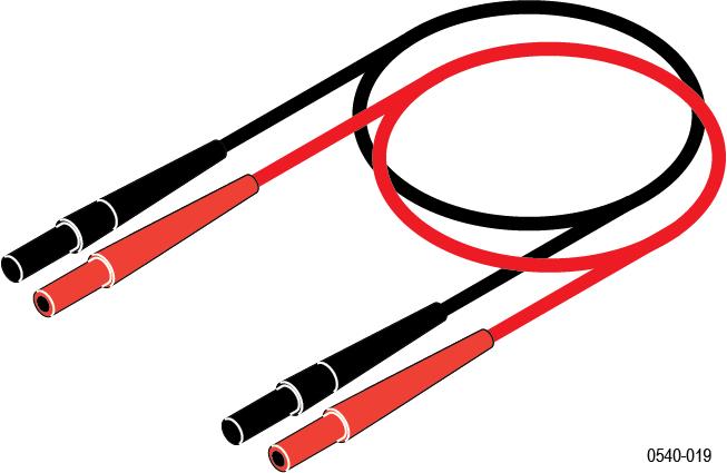
Extender Leads
These leads extend the reach of the probes by 1.0 m, which allow you to reach connections as far as 3.5 m apart. Be sure to use both extension leads so that the input leads are the same length.
However, with longer lead length, differential noise induced into the input leads is greater. Also, because of the added inductance of the leads, voltage measurements at frequencies above approximately 10 MHz may not be as precise. For best performance, use the 20 MHz or lower-bandwidth filter on your oscilloscope.
The male banana-plug ends connect to the test probes that are included with the probes.
One pair of extender leads are included with the probes.
- Maximum ratings:
- 1000 V CAT III
Reorder Tektronix part number: 196-3523-xx
THDP0100 Probe Accessory Kit
- Test Probes (TATP)
- Small Hook Tips TASH)
- Large Hook Tips (TALH)
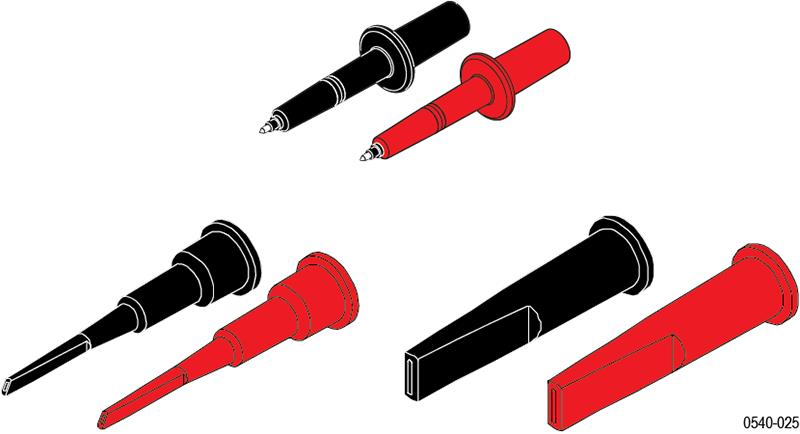
Reorder Tektronix part number: 020-3070-xx
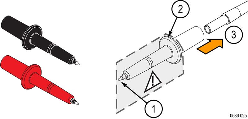
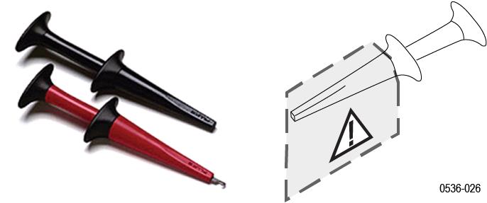
Test Probes (TATP)
- The test probe tip is a 6-32 threaded post that accepts the large and small hook tips provided with the probe.
- The finger guard provides protection when the hook tips are not being used. Keep your fingers behind the finger guard whenever possible to reduce the risk of a shock from the circuit under test.
- Connect the back end of the test probe to the input test leads of the probe.
- Maximum ratings:
- 2300 V CAT I. See the Specifications for the Over-Voltage Transient (OVT) rating for the probe that you are using. Typical characteristics.
| WARNING:To prevent arc flash, use caution when probing circuits with raised components. Avoid getting the metal shell between components of different potentials. Use the small hook tip (TASH) for probing in hard to reach areas. |
| WARNING:To prevent arc flash, do not use the test probe or hook tips on CAT III circuits. To probe CAT III circuits, use the AC280-FL, AC283-FL, or AC285-FL accessories. |
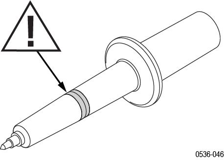
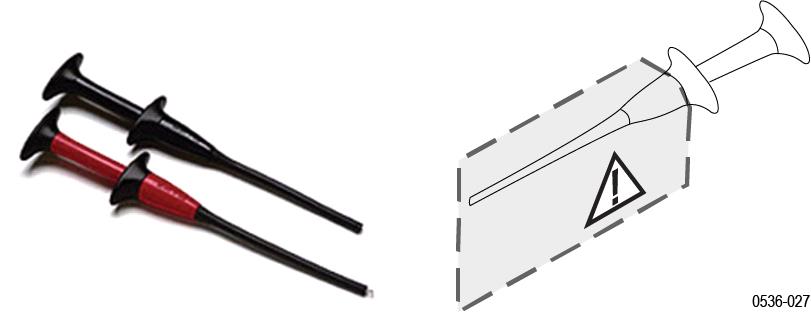
Small Hook Tip (TASH)
Use the small hook tip for making connections to small conductors such as component leads.
Screw the small hook tip onto the TATP test probe. To use the hook tip, hold the probe body and pull the tip shield back. Hook the tip onto the circuit and release the shield.
| WARNING:To reduce the risk of shock when measuring voltages above 1000 V, always keep your fingers behind the tactile indicator. |
- Maximum ratings:
- 2300 V CAT I. See the Specifications for the Over-Voltage Transient (OVT) rating for the probe that you are using. Typical characteristics.
Large Hook Tip (TALH)
Use the large hook tip when working with larger components such as bolt terminals and bus bars typically found in power distribution equipment. Screw the large hook tip onto the TATP test probe and then clamp the hook tip onto the circuit.
| WARNING:To reduce the risk of shock when measuring voltages above 1000 V, always keep your fingers behind the tactile indicator. |
- Maximum ratings:
- 2300 V CAT I. See the Specifications for the Over-Voltage Transient (OVT) rating for the probe that you are using. Typical characteristics
Voltage derating for THDP0100 probe standard accessories
The THDP0200 and TMDP0200 standard accessories can be used with the THDP0100 probe at the reduced voltage levels listed in this table.
| Accessory | THDP0100 | THDP0200 | TMDP0200 |
|---|---|---|---|
| Extender leads (196-3523-xx) | 2300 V CAT I 1000 V CAT III | 1000 V CAT II 600 V CAT III | 550 V CAT I 300 V CAT III |
| Test probe (TATP) (part of 020-3070-xx kit) | 1000 V CAT I 1000 V CAT II | 1000 V CAT II 600 V CAT II | 550 V CAT I 300 V CAT II |
| Small hook tip (TASH) (part of 020-3070-xx kit) | 2300 V CAT I 1000 V CAT II | 1000 V CAT II 600 V CAT II | 550 V CAT I 300 V CAT II |
| Large hook tip (TALH) (part of 020-3070-xx kit) | 2300 V CAT I 1000 V CAT II | 1000 V CAT II 600 V CAT II | 550 V CAT I 300 V CAT II |
Voltage derating for THDP0200 and TMDP0200 probe standard accessories
The operating altitude of the probe is derated to 2000 m (6560 ft) when used with these accessories.
The voltage rating and CAT rating are derated to the voltage in this table when used with these accessories.
| Accessory | THDP0100 | THDP0200 | TMDP0200 |
|---|---|---|---|
| Extender leads (196-3523-xx) | 2300 V CAT I 1000 V CAT III | 1000 V CAT II 600 V CAT III | 550 V CAT I 300 V CAT III |
| Handheld probes (TP175) | 1000 V CAT I 1000 V CAT III | 1000 V CAT II 600 V CAT III | 550 V CAT I 300 V CAT III |
| Pogo pin tip adapters and tips (020-3107-xx) | 150 V CAT II | 150 V CAT II | 150 V CAT II |
| Extended test probe adapters (012-1724-xx) | 300 V CAT I300 V CAT II | 300 V CAT II | 300 V CAT I300 V CAT II |
| Hook clips (AC280-FL) | 1000 V CAT I 1000 V CAT III | 1000 V CAT II 600 V CAT III | 550 V CAT I 300 V CAT III |
| Pincer clips (AC283-FL) | 1000 V CAT I 1000 V CAT III | 1000 V CAT II 600 V CAT III | 550 V CAT I 300 V CAT III |
| Alligator clips (AC285-FL) | 1000 V CAT I 1000 V CAT III | 1000 V CAT II 600 V CAT III | 550 V CAT I 300 V CAT II |
| Crocodile clips (344-0670-xx) | 300 V CAT I | 300 V CAT I | 300 V CAT I |
The THDP0100 probe can be used with these accessories at the reduced voltage levels listed in this table.
When using the TP175 test probes in CAT III circuits, the tip must be in the retracted position to prevent risk of arc flash. The exposed metal tip is about 3.7 mm (0.15 in) in the retracted position.
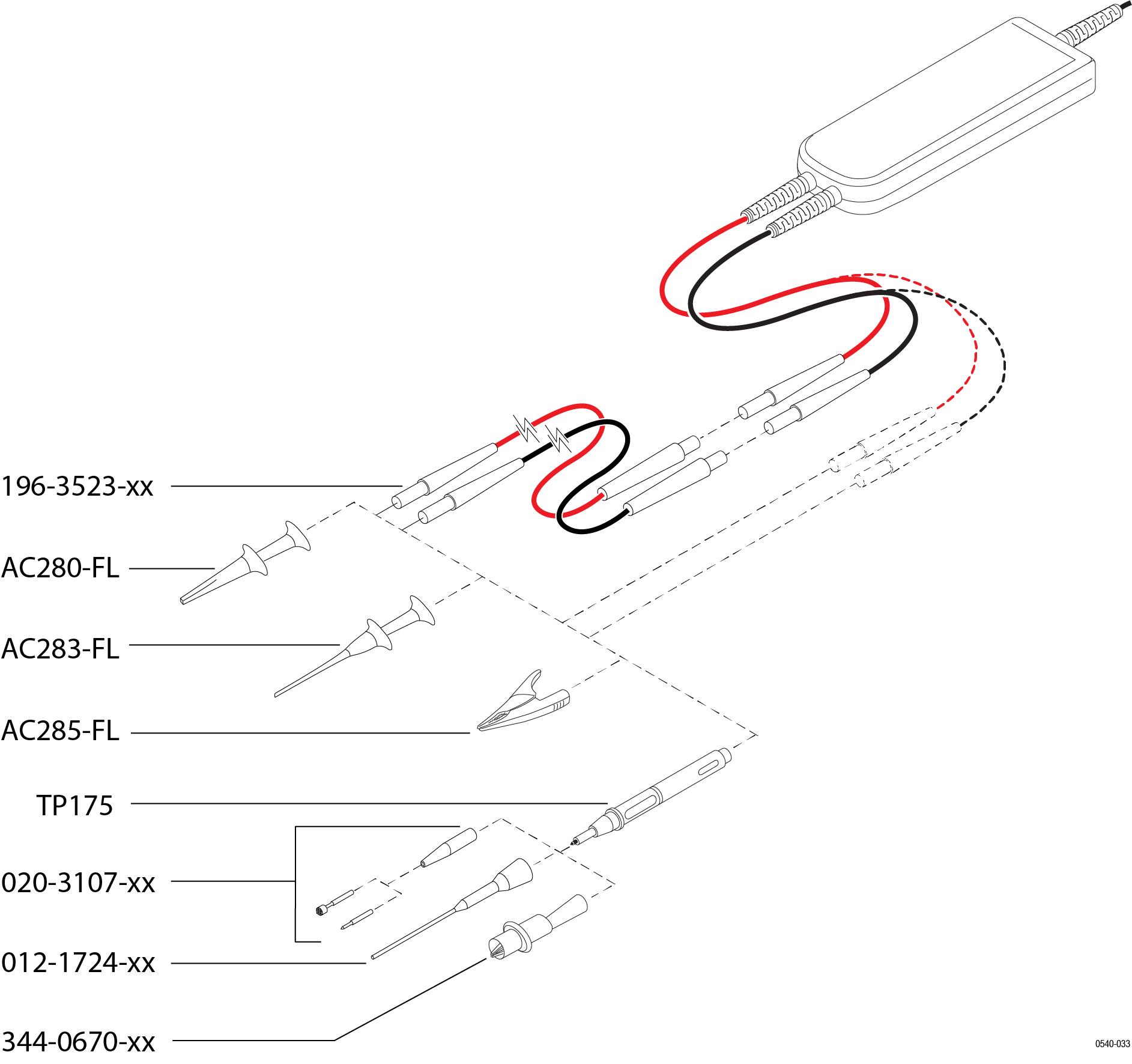
THDP0200 and TMDP0200 probe standard accessories
The standard accessories that connect directly to your circuit are shown below, and are described on the following pages.
| WARNING:To reduce risk of shock or fire, do not exceed either the voltage rating or category ratings of the probe or the probe accessory, whichever is the lesser of the two. Use only the accessories provided with the probe. To avoid electric shock when using the probe or accessories, keep your fingers behind the finger guard of the probe body and away from the shaded area shown in the accessory illustrations below. |
Extender Leads
These cables extend the reach of the probes by 1.0 m. The banana ends connect to all of the clip accessories that are included with the probes.

- Maximum ratings:
- 2300 V CAT I. See the Specifications for the Over-Voltage Transient (OVT) rating for the probe that you are using. Typical characteristics.
One pair of extender leads are included with the probes.
Reorder Tektronix part number:196-3523-xx (one pair)
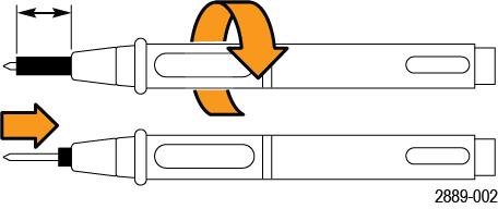
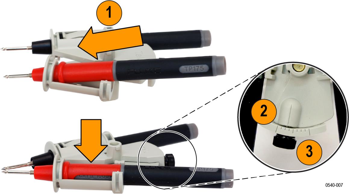
Handheld Probes (TP175)
These probes plug onto the banana input leads and extender leads. The tips are threaded to accept tip accessories. The insulator sheath at the probe tip extends and retracts into CAT III and CAT IV-rated spacings. Twist the probe body past the detent at each end of the twist to lock the probe into the CAT setting.
The insulator sheath at the probe tip extends and retracts into CAT III and CAT IV-rated spacings. Twist the probe body past the detent at each end of the twist to lock the probe into the CAT setting.
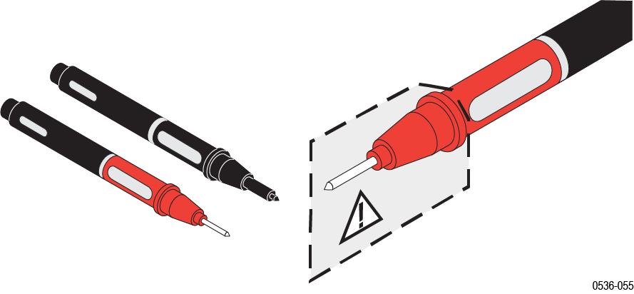
| WARNING:Always verify that the probe body is locked into position before taking measurements. Do not use in the unlocked neutral position. |
- Maximum ratings:
- 1000 V CAT II
One pair of handheld probes are included with the probes.
| Note:The TP175 must be ordered through Fluke. |
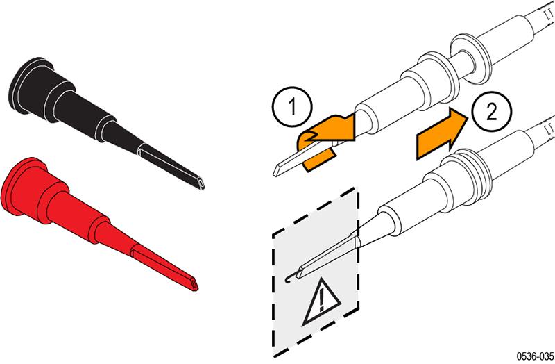
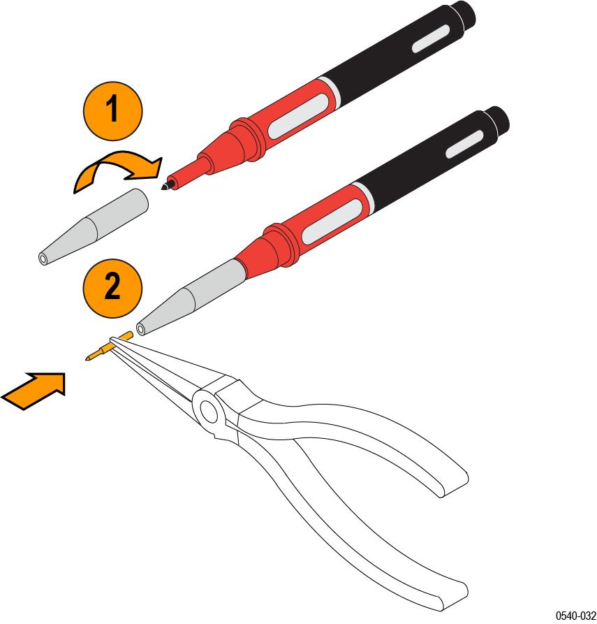
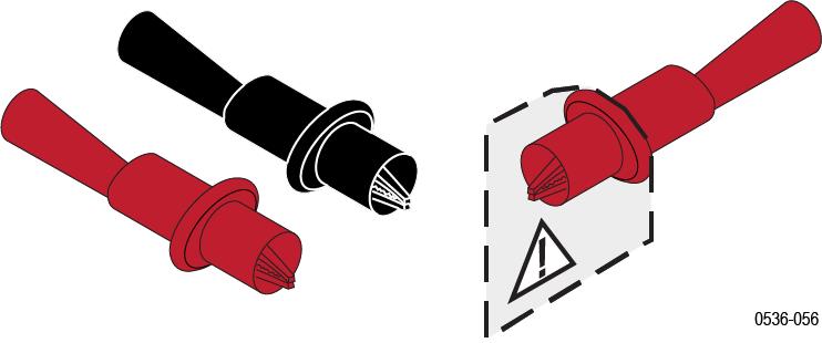
Pogo Pin Tip Adapters and Tips
These insulated adapters hold pogo pins and screw on to the threaded tips of the TP175 handheld probes.
| WARNING:To prevent electrical shock, tighten the pogo pin tip adapter completely to the TP175 probe. |
Two pairs of pogo pin types are included with the adapters; one pair have sharp, cone points and the other pair have serrated edges for embedding in soft conductors.
| WARNING:The pogo pins have very sharp points. To prevent injury, handle the pins carefully when you install and remove them. |
| WARNING:To prevent risk of arc flash, ensure that the pogo pin is completely inserted into the adapter. Verify that the exposed metal portion of the tip is 19 mm (0.75 in) or less. |
| WARNING:The probe input rating is derated to 150 V CAT II, 1 mA, when used with the THDP and TMDP series probes. Do not use this pogo pin adapter to measure voltages that exceed this rating. |
- Maximum ratings:
- 150 V CAT II
Reorder Tektronix part number: 020-3107-xx (includes 2 Tip Adapters, 2 Cone-Tip Pogo Pins, and 2 Serrated-Tip Pogo Pins)
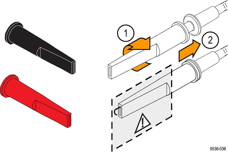
Extended Test Probe Adapters
These adapters screw on to the threaded tips of the handheld probes. Use these adapters to reach into dense circuitry. The sharp tips can contact small component leads and circuit board features.
| WARNING:The probe input rating is derated to 150V CAT II, 1 mA, when used with the THDP and TMDP series probes. Do not use this extended probe adapter to measure voltages that exceed this rating. |
| WARNING:The tip on this adapter is very sharp. To prevent injury, do not touch the tip. |
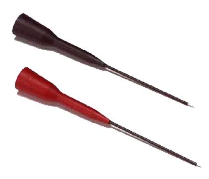
- Maximum ratings:
- 300 V CAT II
Reorder Tektronix part number: 012-1724-xx (one pair)
Hook Clips (AC280-FL)
Plug the probe test leads into the banana plug connectors. Squeeze the grips to expose the hook clip and then clasp it around the circuit test point.
- Maximum ratings:
- 1000 V CAT III
One pair of hook clips are included with the probes.
Reorder Tektronix part number: AC280-FL (one pair)
Pincer Clips (AC283-FL)
The plunger probes have long probe sleeves with retracting hooks. These probes safely connect to recessed test points that are otherwise difficult to reach.
- Maximum ratings:
- 1000 V CAT III
One pair of pincer clips are included with the probes.
Reorder Tektronix part number: AC283-FL (one pair)
Alligator Clips (AC285-FL)
These large insulated alligator clips connect to many circuit components.
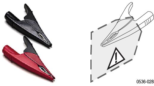
- Maximum ratings:
- 1000 V CAT III
One pair of clips are included with the probes.
Reorder Tektronix part number: AC285-FL (one pair)
Crocodile Clips
The crocodile clips connect easily to large bolts or bus bars. The connectors are double insulated for safety. The clips screw on to the threaded tips of the handheld probes.
- Maximum ratings:
- 1000 V CAT III
One pair of clips is included with the probes.
Reorder Tektronix part number: 344-0670-xx (one pair)
TPH1000 probe holder
The TPH1000 probe holder allows you to make a hands-free connection when using the handheld probes included in the accessory kit. The probe holder can also be used with many other Tektronix probes.
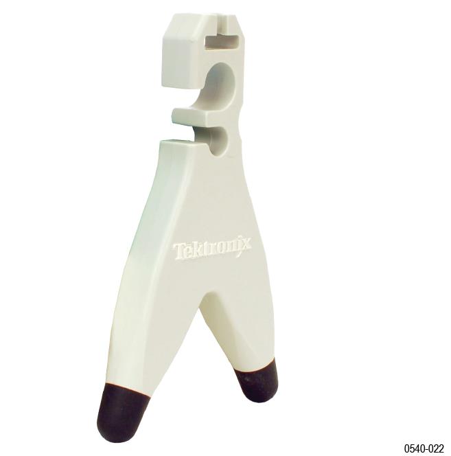
- You can use the handheld probes with two TPH1000 probe holders (required if the test points are >1 inch apart).
- For test points <1 inch apart, use the handheld probes with the THV-Browser (shown on the following page).
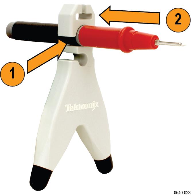
- Insert the probe into one of the holder openings so that the Tektronix logo faces the circuit under test.
- Slide the probe forward to secure it.CAUTION:To avoid personal injury, always insert and remove probes by gripping the handheld section of the probe.
- Position the base of the probe holder on your circuit where it can maintain stability while contacting the test point.WARNING:Do not use the probe holder without the rubber feet; internal metal would be exposed which presents a shock hazard.
The weight of the probe holder keeps the probe in place.
| CAUTION:If you are probing circuitry with dense contacts such as IC pins, Tektronix recommends that you use insulated probe tip accessories designed to prevent short-circuiting adjacent IC pins or circuitry. |
One TPH1000 probe holder is included with the probes.
Reorder Tektronix part number: TPH1000
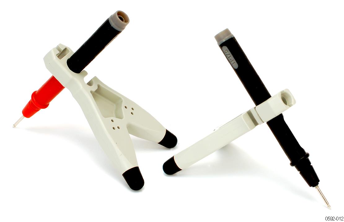
THV-Browser
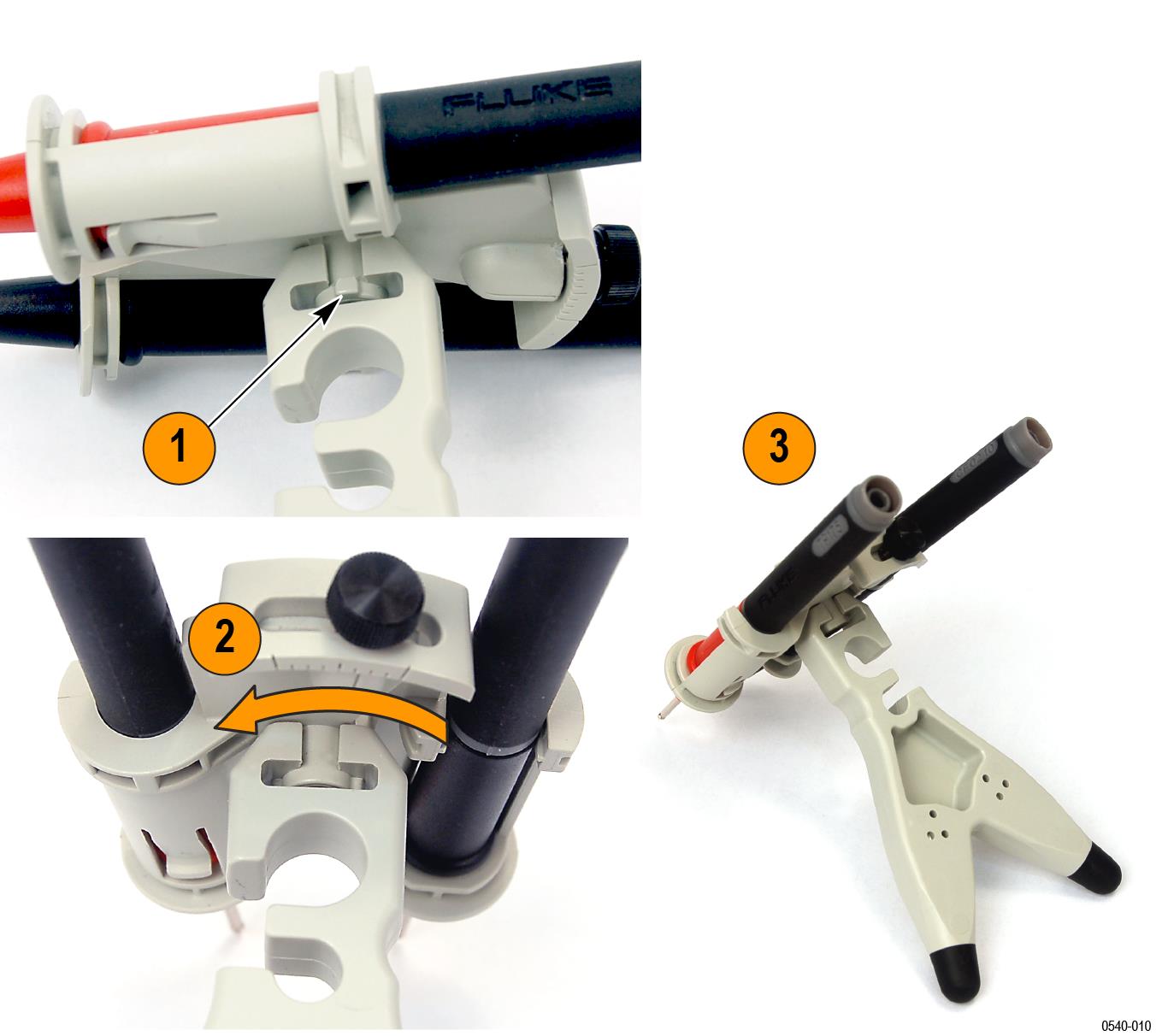
The THV-Browser allows you to set and lock the spacing between two handheld probe tips, and then browse your circuit with one hand.
- Place each handheld probe lead into the cavity and then slide the probe forward to secure it.
- Loosen the thumb screw and adjust the spacing between the probe tips. Graticules near the thumb screw indicate the spacing. The maximum spacing is ~1 in (2.54 mm).
- Tighten the thumb screw. You can now browse your circuit.
| WARNING:To avoid injury or short circuits, do not drop the THV-Browser on high voltage circuitry. The browser contains metal components. |
- Align the slots on the top of the probe holder with the pins on the bottom of the browser.
- Rotate the browser 90°.
- Position the probe tips on your test points so that you can set the holder on a stable surface.
One THV-Browser is included with the probes.
Reorder Tektronix part number: THV-Browser
THDP and TMDP Series probes optional accessories
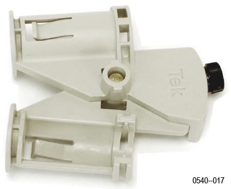
TekVPI Calibration Fixture
This calibration fixture is required to complete a performance verification and adjustment procedures on the probe. It provides power to the probe and routes the probe output signal through an SMA connector on the back of the fixture.
The signal can then be measured with another instrument, (for example, a precision DMM), to check and adjust probe qualities such as gain accuracy.
Order Tektronix part number: 067-1701-xx
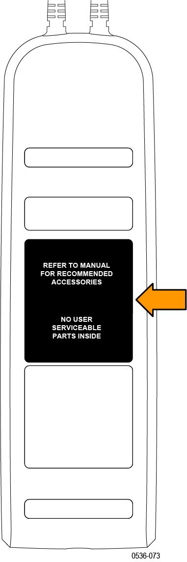
Replacement Label (Safety Item; Service Only)
This reusable label covers the openings to the service-only adjustments on the back of the probe. To maintain the safety of the probe, the label must be replaced after service adjustments are made to the probe.
If the original label becomes damaged or lost, order a replacement label.
Order Tektronix part number: 335-2913-xx
Service Options
- Option C3
- Calibration Service 3 years
- Option C5
- Calibration Service 5 years
- Option D1
- Calibration Data Report
- Option D3
- Calibration Data Report, 3 years (with Option C3)
- Option D5
- Calibration Data Report, 5 years (with Option C5)
- Option R3
- Repair Service 3 years
- Option R5
- Repair Service 5 years
Operating basics
To help you use the high voltage differential probes safely and effectively, this section provides important information about safety limits, operating characteristics, and probing techniques.
Operating limits
The probes have two operating ranges that you select with the RANGE button; the ranges differ between probe models.
To keep within the linear measurement region of the probe, select a range that is above the differential voltage that you are measuring. You can measure a voltage in the low range that exceeds the low range limit (provided it is within the high range limit of the probe), but it will overdrive the circuitry of the probe. When this differential overrange occurs, the probe detects the condition and lights the OVERRANGE indicator. Measurements taken in the lower, more sensitive range when the OVERRANGE indicator is lit are not accurate during the Overdrive Recovery Time (ORT, typically <20 ns, depending on the probe type).
Do not attempt to measure a differential voltage that is above the high operating range of the probe. Do not exceed the common mode voltage on either input (+ or – input to ground). See Typical characteristics. The probe can be damaged if these limits are exceeded.
| Low range | High range | |||
|---|---|---|---|---|
| Probe model | Voltage limit | Overload trip level | Voltage limit | Overload trip level |
| THDP0100 | 600 V | >600 V | 6000 V | >6000 V |
| THDP0200 | 150 V | >150 V | 1500 V | >1500 V |
| TMDP0200 | 75 V | >75 V | 750 V | >750 V |
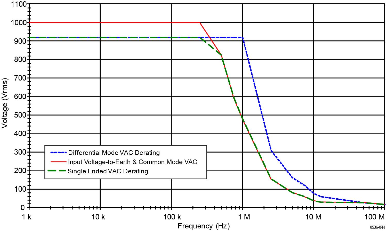
The input signals that you attempt to measure must be considered both for the differential potential between each other and for the amplitude on each input with respect to ground (the common mode voltage specification). The maximum common mode voltage limits vary between probes, from 550 V CAT I for the TMDP0200, to 2300 V CAT I for the THDP0100 probe. You should consider both specifications when choosing a probe for your measurement task. Some examples that illustrate this are shown on the following pages.
Measurement examples
Example 1
Consider a case where you need to measure two sinusoidal waveforms that are 180° out of phase with each other, each with an amplitude of 1000 Vpk with no DC offset (centered at 0 V).
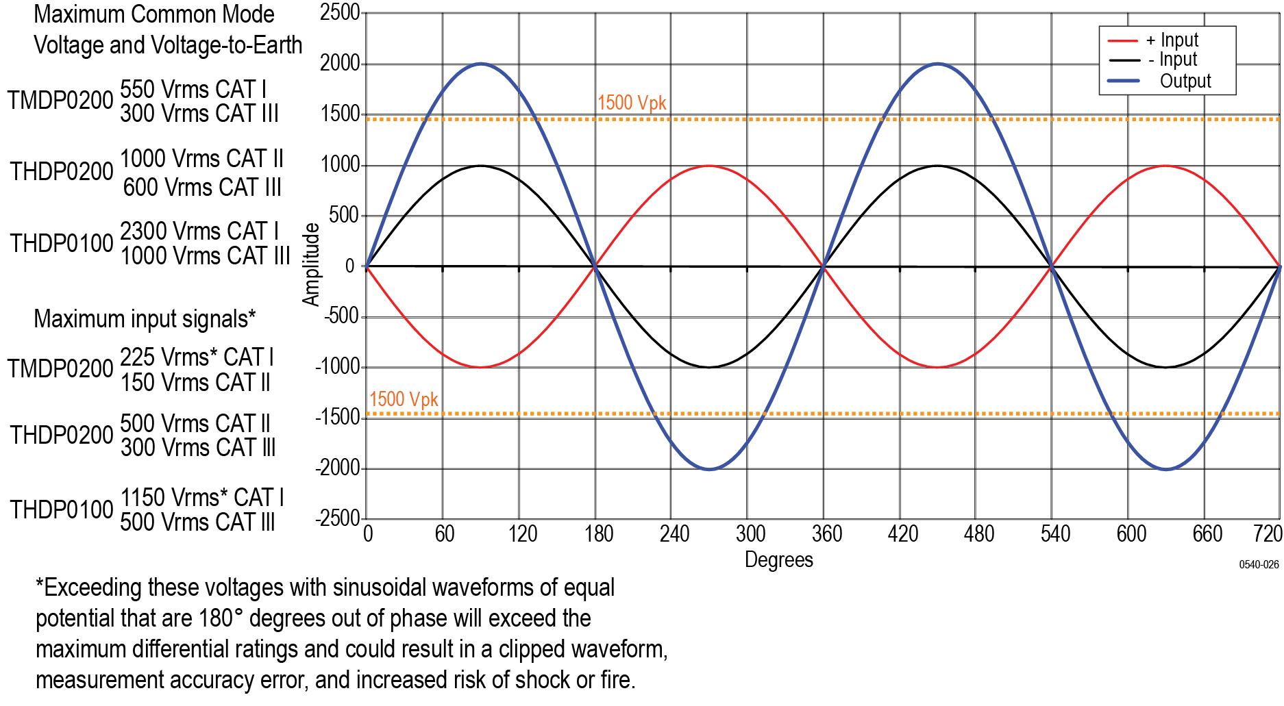
If both waveforms are at the same voltage potential, then the differential measurement would be 2 times the individual signal inputs (in this example, 2000 Vpk). Looking at the maximum measurable differential voltage specifications for the THDP/TMDP series probes, the THDP0100 probe is capable of measuring this signal. See Typical characteristics. For reference, the rms values of the Common-Mode Voltage and Voltage-to-Earth ratings and Maximum Input Signals for each probe model are shown in the figure above.
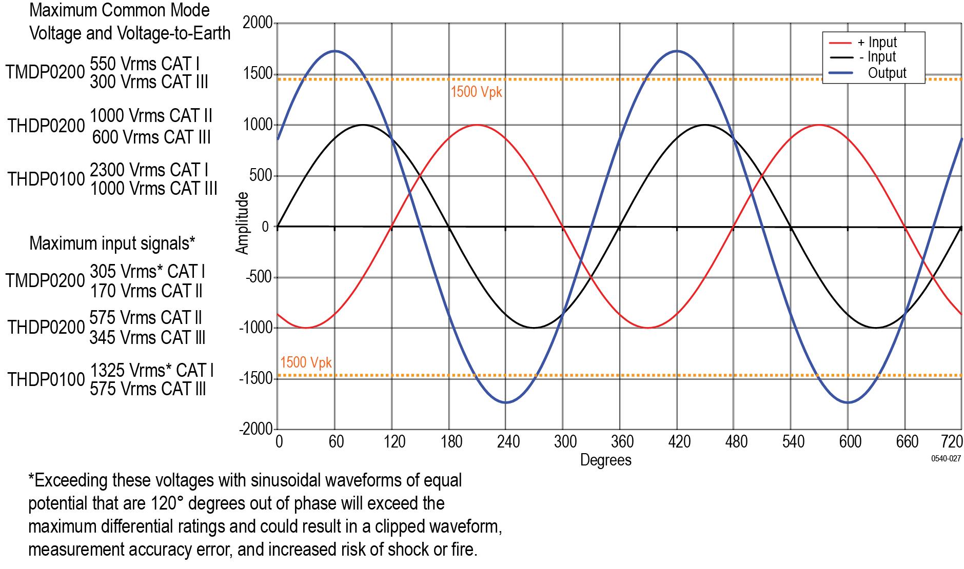
Example 2
Next, assume that the same waveforms from the previous example are 120° out of phase with each other. This phase relationship yields a maximum differential of 1.732 times the individual signal inputs, or 1732 Vpk. Although this is a lower potential between the inputs than in example 1, it exceeds the differential voltage ratings of the THDP0200 and TMDP0200 probes, so you must use the THDP0100 probe.
Example 3
Your task is to measure two AC waveforms of the same phase, each with an amplitude of 300 V. However, one waveform is centered on ground (– input), and the other is centered on an offset of 400 VDC (+ input). The common mode voltage is the 300 Vrms, but the maximum voltage-to-earth (the common mode voltage plus the signal waveform) must also be taken into account for both inputs. The voltage-to-earth is 300 Vrms on the (– input), but on the (+ input), the voltage-to-earth is 700 Vrms (the 300 VACrms plus the 400 VDCrms). Thus the (+ input) exceeds the maximum input voltage-to-earth rating of the THDP0200 probe, so it cannot be used for taking this measurement. In this case, you must use either the TMDP0200 or THDP0100 probe.
Overrange detection
Differential voltage outside the operating range will overdrive the circuitry of the probe and distort the output signal. When this differential overrange occurs, the probe detects the condition and lights the overrange indicator. With the Audible Overrange ON, the probe will also emit an audible alarm.
| WARNING:The Overrange indicator does not detect an overrange condition of common-mode voltages or voltage-to-earth potential at the probe inputs. The Overrange indicator only detects differentially between the + and – inputs (not relative to ground). Do not exceed the Common-Mode Voltage or Input Voltage-to-Earth ratings of the probe when taking measurements. If you are not sure, first take a single-ended measurement of each point that you are intending to measure differentially. Take a single-ended measurement by tying one input lead to ground (the – input) and then connecting the other lead (the + input) to the points of interest, one at a time. |
Common-mode rejection
The common-mode rejection ratio (CMRR) is the specified ability of a probe to reject signals that are common to both inputs. More precisely, CMRR is the ratio of the differential gain to the common-mode gain. The higher the ratio, the greater the ability of probe to reject common-mode signals.
Common mode rejection decreases as the input frequency increases. For example, if you apply a 60 Hz line voltage of 500 Vp-p to both input leads of the probe, the probe rejects the signal by 80 dB (typical) and the signal appears as only a 50 mVp-p signal on the oscilloscope screen.
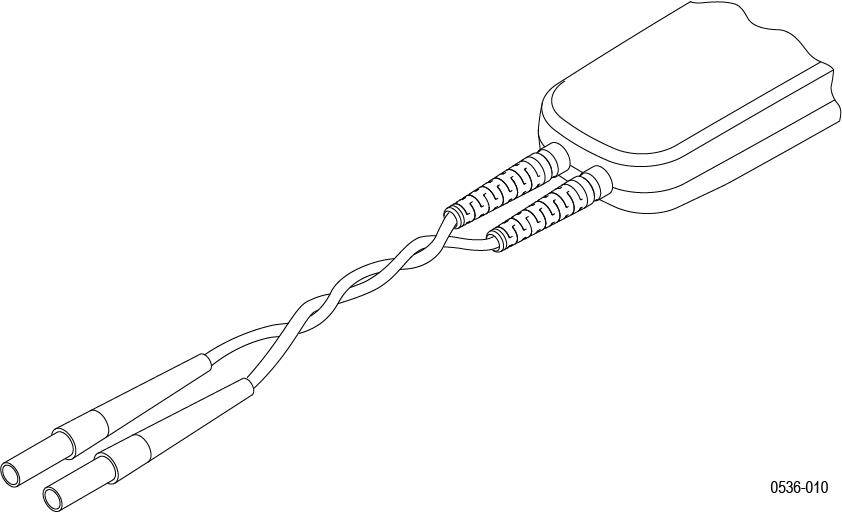
Twisting the input leads
Twisting the input leads helps to cancel noise from high-EMI environments that is induced into the input leads.
Probe Loading
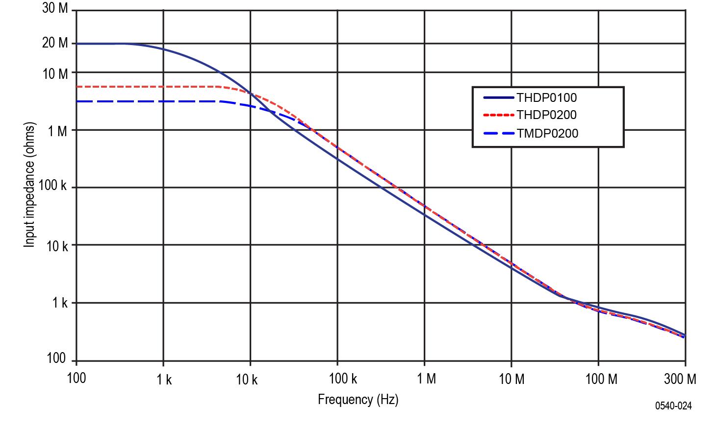
When you touch your probe tip to a circuit element, you are introducing a new resistance, capacitance, and inductance into the circuit. Frequency and impedance of the source determine how much the probe loads the circuit you are measuring. As the frequency of the source starts to increase beyond 1 kHz, the input impedance of the probe begins to decrease.
The lower the impedance of the probe relative to that of the source, the more the probe loads the circuit under test. For a graph of frequency versus input impedance, refer to the Specifications section. As the graph shows, the probes have virtually no loading effect on sources with relatively low impedance and low frequency.
Specifications
The specifications shown apply to the THDP/TMDP series probes installed on Tektronix MSO/DSO4000 oscilloscopes. When a probe is used with another oscilloscope, the oscilloscope must have an input impedance of 1 MΩ and a bandwidth equal to or greater than the probe. The probe must have a warm-up period of at least 20 minutes and be in an environment that does not exceed the limits described. See Table 2. Specifications for the THDP/TMDP series probes fall into three categories: warranted, typical and nominal characteristics.
Warranted specifications
Warranted characteristics describe guaranteed performance within tolerance limits or certain type-tested requirements.
| Characteristics | THDP0100 | THDP0200 | TMDP0200 |
|---|---|---|---|
| Rise time (small signal, 10–90%, +20 °C to +30 °C). Output may be slew rate limited for large amplitude signals. | 600 V: ≤3.6 ns(typical: ≤3.5 ns) | 150 V: ≤2.4 ns(typical: ≤2.2 ns) | 75 V: ≤2.4 ns(typical: ≤2.2 ns) |
| 6000 V: ≤3.6 ns(typical: ≤3.5 ns) | 1500 V: ≤2.0 ns(typical: ≤1.8 ns) | 750 V: ≤2.0 ns(typical: ≤1.8 ns) | |
| (slew rate ≥2500 V/ns (6000 V)) | (slew rate ≥650 V/ns (1500 V)) | (slew rate ≥275 V/ns (750 V)) | |
| DC gain accuracy | ±2% | ±2% | ±2% |
| Characteristics | THDP0100 | THDP0200 | TMDP0200 |
|---|---|---|---|
| Operating Temperature | 0 °C to 40 °C (32 °F to +104 °F) | ||
| Nonoperating Temperature | –30° C to +70° C (–22 °F to +158 °F) | ||
| Operating Humidity | 5 to 85% RH (Relative Humidity) 0 °C to +40 °C (32 °F to +104 °F) | ||
| Nonoperating Humidity | 5% to 85% RH at up to +40° C (+104 °F). 5% to 45% RH above +40° C up to +70° C (+104 to +158 °F) | ||
| Operating Altitude | 3,000 m (9,842 ft) | ||
| Nonoperating Altitude | 15,240 m (50,000 ft) | ||
Typical characteristics
Typical characteristics describe typical but not guaranteed performance.
| Characteristics | THDP0100 | THDP0200 | TMDP0200 |
|---|---|---|---|
|
Maximum measurable differential voltage. This is the maximum measurable range of the probe. Beyond these limits, the output could be clipped. | 600 V Range: 600 V DC + peak AC, 450 Vrms | 150 V Range: 150 V DC + peak AC, 100 Vrms | 75 V Range: 75 V DC + peak AC, 50 Vrms |
| 6000 V Range: 6000 V DC + peak AC, 3000 Vrms | 1500 V Range: 1500 V DC + peak AC, 1000 Vrms | 750 V Range: 750 V DC + peak AC, 500 Vrms | |
|
Maximum common mode voltage and input voltage-to-earth. The Common Mode ratings are the same as the input voltage-to-earth ratings (the maximum amount that each input lead (+/-) can be from ground). | ±6000 V DC + peak AC, 2300 V CAT I, 1000 V CAT III | ±1500 V DC + peak AC, 1000 V CAT II, 600 V CAT III | ±750 V DC + peak AC, 550 V CAT I, 300 V CAT III |
|
CAT I Maximum Rated Over- Voltage Transient (OVT). Applies to CAT I ratings only (both ranges). The OVT peak is typically measured on top of the Peak Working Voltage. | 4600 Vpk | NA | 3220 Vpk |
| Bandwidth (-3 dB) | DC to ≥100 MHz | 150 V: DC to ≥160 MHz | 75 V: DC to ≥160 MHz |
| 1500 V: DC to ≥200 MHz | 750 V: DC to ≥200 MHz | ||
| Offset zero (+20 °C to +30 °C) | 600 V: ±1 V | 150 V: ±500 mV | 75 V: ±200 mV |
| 6000 V: ±10 V | 1500 V: ±5 V | 750 V: ±2 V | |
| Input resistance between inputs | 40 MΩ ±2% | 10 MΩ ±2% | 5 MΩ ±2% |
| Input resistance between each input and ground | 20 MΩ ±2% | 5 MΩ ±2% | 2.5 MΩ ±2% |
| Input capacitance between inputs | <2.5 pF | <2.0 pF | <2.0 pF |
| Input capacitance between each input and ground | <5.0 pF per side | <4.0 pF per side | <4.0 pF per side |
| Common Mode Rejection Ratio (20–30°C) | DC: >80 dB | DC: >80 dB | DC: >80 dB |
| 100 kHz: >60 dB | 100 kHz: >60 dB | 100 kHz: >60 dB | |
| 3.2 MHz: >30 dB | 3.2 MHz: >30 dB | 3.2 MHz: >30 dB | |
| 100 MHz: >26 dB | 100 MHz: >26 dB | 100 MHz: >26 dB | |
| Propagation delay | 16 ns | 14 ns | 14 ns |
| DC offset drift (output referred) | 50 μV/ °C | 50 μV/ °C | 50 μV/ °C |
| Bandwidth limit filters | 5 MHz | 5 MHz | 5 MHz |
| Input overdrive recovery | 600 V: <30 ns to 10% of final value after 5X overdrive | 150 V: <20 ns to 10% of final value after 5X overdrive | 75 V: <20 ns to 10% of final value after 5X overdrive |
| Input referred noise (mVrms) | 600 V: <175 mV | 150 V: <50 mV | 75 V: <25 mV |
| 6000 V: <400 mV | 1500 V: <140 mV | 750 V: <65 mV |
Mechanical characteristics
| Characteristic | THDP0100 | THDP0200 | TMDP0200 |
|---|---|---|---|
| Probe body dimensions | 185 mm x 56 mm x 25 mm (7.3 in x 2.2 in x 1.0 in) | ||
| Probe control box dimensions | 76 mm x 31 mm x 41 mm (3.0 in x 1.2 in x 1.6 in) | ||
| Input cable length | 25.4 cm (10 in) | ||
| Output cable length | 1.5 m (59 in) | ||
| Weight (probe only) | 340 gm (12.0 oz) | 309 gm (10.9 oz) | 309 gm (10.9 oz) |
Nominal characteristics
Nominal characteristics describe guaranteed traits, but the traits do not have tolerance limits.
|
Characteristics |
THDP0100 |
THDP0200 |
TMDP0200 |
|---|---|---|---|
| Number of inputs | Differential (two inputs, + and – ) | ||
| Input coupling | DC | ||
| Output coupling | DC coupling | ||
| Output termination | Terminate into 1 MΩ | ||
| Attenuation | 100X/1000X | 50X/500X | 25X/250X |
| (600 V/6000 V) | (150 V/1500 V) | (75 V/750 V) | |
| Differential overvoltage detection level | 600 V: >600 V | 150 V: >150 V | 75 V: >75 V |
| 6000 V: >6000 V | 1500 V: >1500 V | 750 V: >750 V | |
The Overrange/overvoltage indicator does not detect common mode voltage or voltage-to-earth potential at the probe inputs. To ensure that the common mode voltage or input voltage-to-earth ratings of the probe are not exceeded, the test points can be measured relative to ground by probing each separately with the + input lead while the – input lead is grounded (by taking a single-ended measurement).
Performance graphs


Performance verification
Use the following procedures to verify the warranted specifications of the probes. Before beginning these procedures, photocopy the test record and use it to record the performance test results. See Test record. The recommended calibration interval is one year.
These procedures test the following specifications:
- Gain accuracy
- Rise time
Required equipment
The equipment required to perform the performance verification procedures are shown in the table below. The types and quantities of connectors may vary depending on the specific equipment you use.
| Description | Minimum requirements | Example product |
|---|---|---|
| Oscilloscope | 500 MHz | Tektronix MSO/DSO4000 |
| Generator | ±100V variable amplitude, 100 Hz square wave, calibrated | Fluke 9100 |
| Pulse generator | ≥50 V, 200 ns pulse width, ≤500 ps rise time, 1 kHz | Avtech AVR-E2-B-W-P |
| Probe calibration fixture | TekVPI input | Tektronix part number 067-1701-xx |
| Digital Multimeter (DMM) | 100 mV and 1 V true RMS AC ranges, <±0.3 % accuracy | Tektronix DMM4040/4050 |
| Cable | Coax, BNC, 50Ω, 36 in | Tektronix part number 012-0482-xx |
|
Adapter |
BNC female-to-SMA male | Tektronix part number 015-1018-xx |
| Adapter | BNC female-to-dual banana female | Tektronix part number 103-0090-xx |
| Adapter | BNC female-to-female | Tektronix part number 103-0028-xx |
| Adapter | BNC male-to-dual banana male | Fluke PM9081 |
| Termination | BNC feedthrough, 50Ω | Tektronix part number 011-0049-xx |
| Attenuator | BNC, 50Ω, 2X | Tektronix part number 011-0069-xx |
| Probe hook tips (2) | Included with probe accessory kit | Tektronix part number AC280–FL |
TekVPI Calibration Fixture
This calibration fixture is required to complete a performance verification and gain accuracy adjustment procedures on the probes. It provides power to the probe and routes the probe output signal out through an SMA connector on the back of the fixture. The signal can then be measured with another instrument, such as a precision DMM, to check and adjust the gain accuracy of the probe. Order Tektronix part number 067-1701-xx.
Test procedures
| WARNING:These procedures require the application of high voltage to the inputs of the probes. Only qualified personnel should perform any testing with voltage levels exceeding 30 Vrms. All pertinent safety rules and guidelines for elevated voltage measurements should be followed and adhered to. |
Test setup
- Turn on the oscilloscope.
- Connect the probe to any channel of the oscilloscope.
- Verify that the LEDs light on the probe.
- Turn on the remaining test equipment and let the probe and equipment warm up for 20 minutes.
- Make a copy of the test record to tabulate the test results. See Test record.
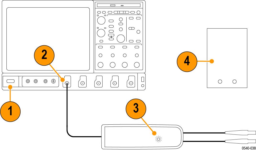
DC gain Accuracy
| WARNING:Dangerous voltages will be present on the calibration generator output terminals and connection cables. Always verify that the generator is in the standby mode before you make any connections to the generator. |
- Verify that the generator output is off.
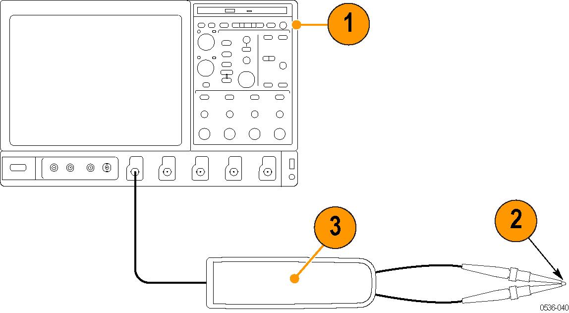
- Connect the probe calibration fixture to any channel (1–4) on the oscilloscope.
- Connect the probe output to the probe calibration fixture and the probe inputs to the generator.
- Connect the output of the probe calibration fixture to the inputs of the DMM, using coax cables and adapters. Set the DMM to AC volts.
- Set the probe attenuation to the lower range for the probe that you are testing. See Table 1.
- Set the generator square wave output frequency and RMS voltage (main display) to the values shown in the table for the probe that you are testing.
- Enable the generator output and record the probe output (as displayed on the DMM) in the test record.
- Disable the generator output.
- Set the probe attenuation to the next range and then repeat steps 6 through 8.
| Probe | Generator output | Probe output voltage | |||
|---|---|---|---|---|---|
| Model | Range | Voltage (rms) | Frequency | Expected (rms) | Measured (rms) |
| THDP0100 | 600 V | 75 V | 100 Hz | 750 mV ±15 mV | |
| 6000 V | 75 V | 100 Hz | 75 mV ±15 mV | ||
| THDP0200 | 150 V | 25 V | 100 Hz | 500 mV ±10 mV | |
| 1500 V | 75 V | 100 Hz | 150 mV ±3 mV | ||
| TMDP0200 | 75 V | 20 V | 100 Hz | 800 mV ±16 mV | |
| 750 V | 60 V | 100 Hz | 240 mV ±4.8 mV | ||
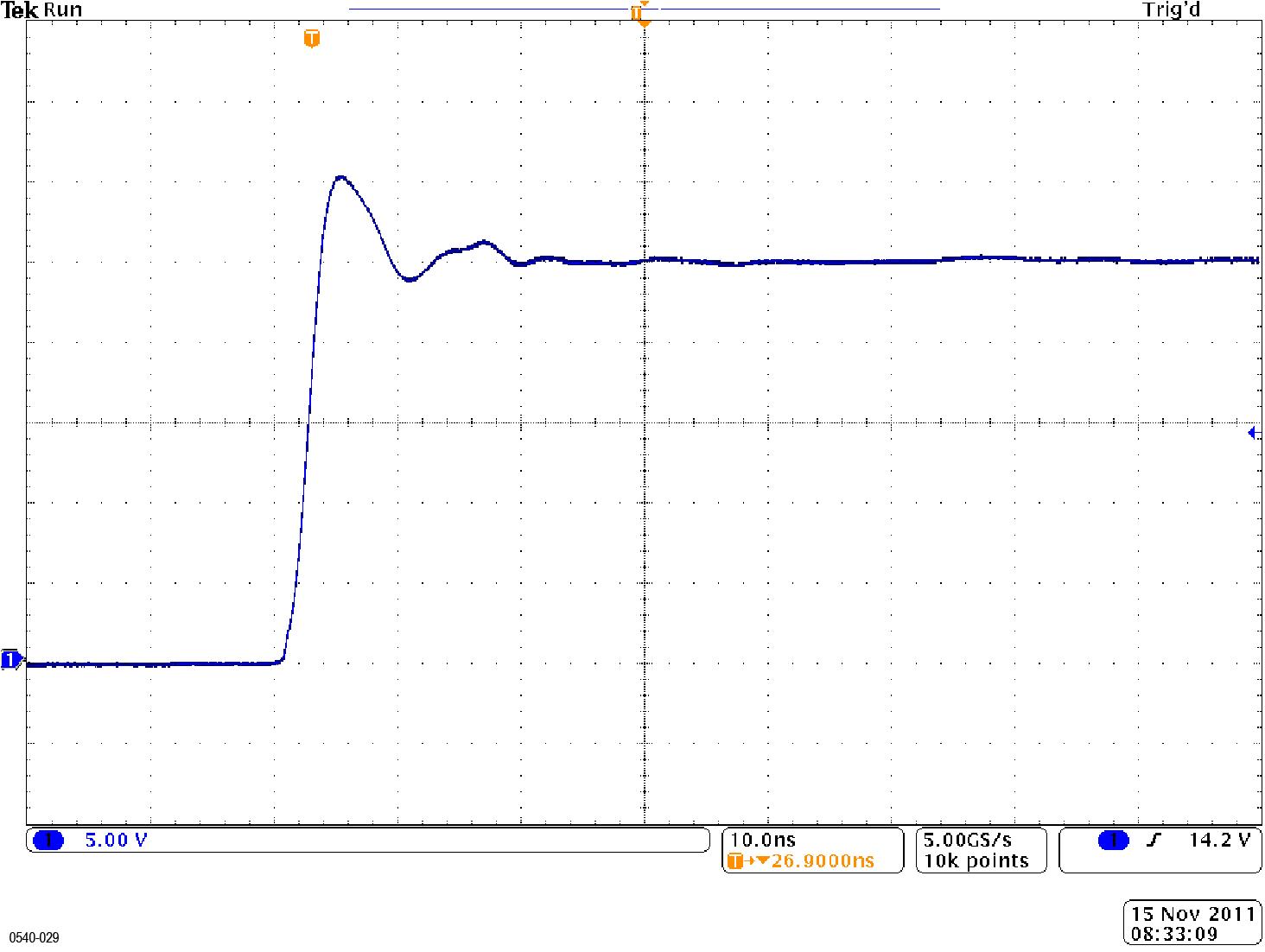
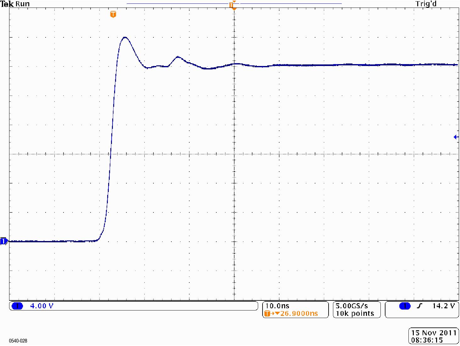
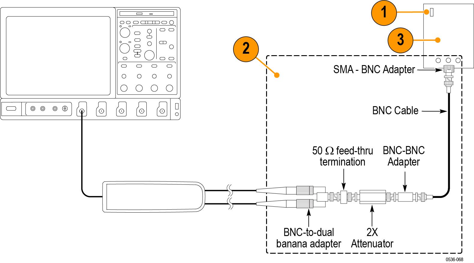
Rise time
- Verify that the pulse generator output is off and then connect the probe to the oscilloscope.
- Connect the probe inputs, through the adapters shown below, to the pulse generator output. Set the probe input leads straight and parallel for best signal response.
- Set the output of the pulse generator to 50 V, 1 kHz, and a 200 ns pulse output. (The probe input voltage will be 25 V due to the 2X attenuator in the circuit.)
- Set the oscilloscope to 5 V/div, 10 ns/div, BW = full, average = 16.
- Set the probe bandwidth to full and the attenuation to the first range listed in the table.
- Enable the generator output and check that the rise time does not exceed the target rise time value listed in the table. Use the auto-measure feature of the oscilloscope to determine the rise time.
- Record the rise time in the test record.
- Set the probe attenuation to the next range and adjust the vertical volts/div to display the signal.
- Record the rise time in the test record and disable the generator output.
| Probe | Generator output | Measurement | |||
|---|---|---|---|---|---|
| Model | Range | Voltage | Frequency | Target | Measured |
| THDP0100 | 600 V | 50 V | 1 kHz | ≤3.6 ns | |
| 6000 V | 50 V | 1 kHz | ≤3.6 ns | ||
| THDP0200 | 150 V | 50 V | 1 kHz | ≤2.4 ns | |
| 1500 V | 50 V | 1 kHz | ≤2.0 ns | ||
| TMDP0200 | 75 V | 50 V | 1 kHz | ≤2.4 ns | |
| 750 V | 50 V | 1 kHz | ≤2.0 ns | ||
Test record
Photocopy this test record for recording the results of the performance verification procedures.
|
Probe Model: Probe Serial Number: Temperature: |
Certificate Number: RH%: Technician: Date of Calibration: | ||||
| Probe test | Range | Minimum | Incoming | Outgoing | Maximum |
|---|---|---|---|---|---|
| THDP0100 gain accuracy | 600 V | 735 mV | 765 mV | ||
| 6000 V | 73.5 mV | 76.5 mV | |||
| THDP0200 gain accuracy | 150 V | 490 mV | 510 mV | ||
| 1500 V | 147 mV | 153 mV | |||
| TMDP0200 gain accuracy | 75 V | 784 mV | 816 mV | ||
| 750 V | 235.2 mV | 244.8 mV | |||
| THDP0100 rise time | 600 V | — | 3.6 ns | ||
| 6000 V | — | 3.6 ns | |||
| THDP0200 rise time | 150 V | — | 2.4 ns | ||
| 1500 V | — | 2.0 ns | |||
| TMDP0200 rise time | 75 V | — | 2.4 ns | ||
| 750 V | — | 2.0 ns |
Adjustments
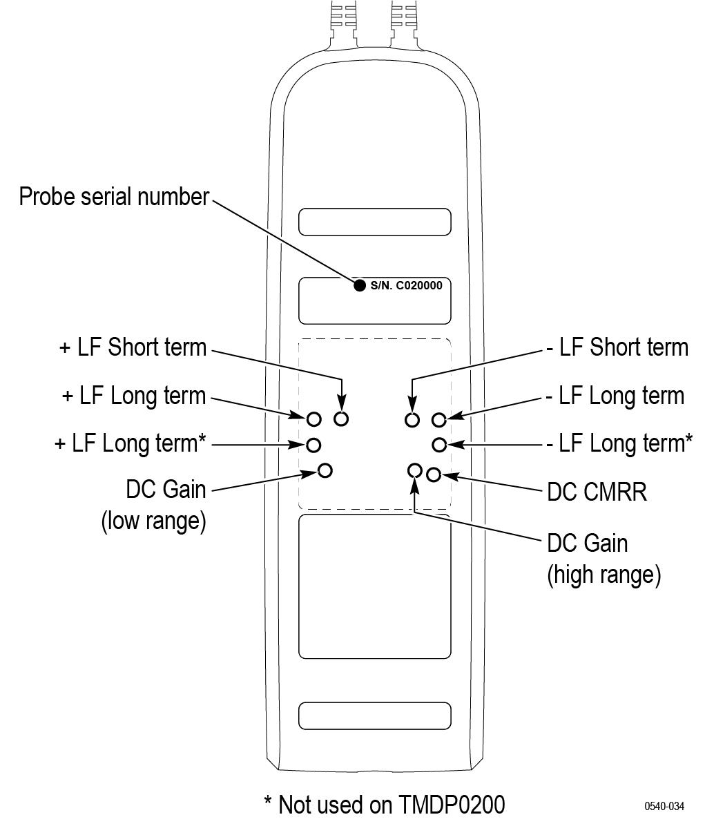
Use the following procedures to make adjustments to the THDP and TMDP Series probes. (For probes with serial numbers C019999 and below, see note and table that follow.) These procedures describe how to make adjustments to the specifications listed below.
| Note:Only probes with serial numbers C020000 and above have internal adjustments. Probes with serial numbers C019999 and below that require adjustments (other than offset zero) must be returned to Tektronix for service. |
| Specification | Adjustment method used | Probe serial number |
|---|---|---|
| Offset zero | External; user probe controls | All serial numbers |
| Gain accuracy | Internal; adjustments on PCB | Serial numbers C020000 and above |
| DC CMRR | Internal; adjustments on PCB | Serial numbers C020000 and above |
| LF compensation | Internal; adjustments on PCB | Serial numbers C020000 and above |
| AC CMRR | Internal; adjustments on PCB | Serial numbers C020000 and above |
| Note:The adjustments in the probes are preset at the factory for best overall performance. However, you may follow these procedures to check the probe characteristics and optimize them if necessary. |
| WARNING:These procedures require you to remove a reusable label from the back of the probe. You must replace the label after you complete the probe adjustments. Failure to do so may subject the user to high voltages present in the probe during measurements. |
Equipment required
The equipment required to perform the adjustment procedures are shown in the table below. The types and quantities of connectors may vary depending on the specific equipment you use.
| Description | Minimum requirements | Example product |
|---|---|---|
| Oscilloscope | 500 MHz | Tektronix MSO/DSO4000 |
| Generator | ±100 V variable, 100 Hz square wave, calibrated | Fluke 9100 |
| Probe calibration fixture | TekVPI inputs | Tektronix part number 067-1701-xx |
| Digital Multimeter (DMM) | 100 mV and 1 V true RMS AC ranges, <±0.3 % accuracy | Tektronix DMM4040/4050 |
| Cable | Coax, BNC, 50 Ω, 36 in | Tektronix part number 012-0482-xx |
| Adapter | BNC female-to-SMA male | Tektronix part number 015-1018-xx |
| Adapter | BNC male-to-dual binding post | Tektronix part number 103-0035-xx |
| Adapter | BNC male-to-dual banana male | Fluke PM9081 |
| Probe hook tips (2) | Included with probe accessory kit | Tektronix part number AC280–FL |
| Adjustment tool | Insulated, slotted (straight) head | Tektronix part number 003-1433-xx |
| Adjustment tool. Required for the CMRR adjustment. | Insulated, narrow-slotted (straight) head | Tektronix part number 003-1928-xx |
| Replacement rear-panel label | Reusable, adhesive-backed label that covers adjustment access openings | Tektronix part number 335-2913-xx |
The original label is backed with a reusable adhesive. If the label does not sufficiently adhere to the probe, order a replacement. Label removal is not required to access offset zero adjustments
Adjustment procedures
| WARNING:These procedures require the application of high voltage to the inputs of the probes. Only qualified personnel should perform any testing with voltage levels exceeding 30 Vrms. All pertinent safety rules and guidelines for elevated voltage measurements should be followed and adhered to. |
Test setup
- Turn on the oscilloscope.
- Connect the probe to any channel of the oscilloscope.
- Verify that the LEDs light on the probe.
- Turn on the remaining test equipment and let the probe and equipment warm up for 20 minutes.
Offset zero
This is the only procedure that applies to all of the probes and all serial numbers.
Adjustment notes
- For probes with serial numbers C199999 and below, Offset Zero is the only adjustment that can be done to the probe.
- For probes with serial numbers C020000 and above, Offset Zero is the only adjustment that can be done without removing the back label.
- The adjustment for each range is independent and does not interact between the ranges.
Procedure
- Set the oscilloscope offset to 0 volts.
- Connect the probe inputs together with the hook tips.
- Press and hold the probe BANDWIDTH LIMIT and RANGE buttons until the OVERRANGE LED on the probe flashes.
- Release the buttons. The OVERRANGE LED continues to flash, indicating that the digitally-controlled offset zero adjustment is enabled.
- Use the probe BANDWIDTH LIMIT and RANGE buttons to set the probe offset voltage as close to 0 V as possible, as displayed on the oscilloscope. The BANDWIDTH LIMIT button decreases the offset voltage and the RANGE button increases it.
- Press the AUDIBLE OVERRANGE button on the probe to store the adjusted offset value. The OVERRANGE LED stops flashing to indicate that the offset value is stored and that the adjustment is disabled.
- Select the remaining attenuation range and repeat steps 3 through 6.
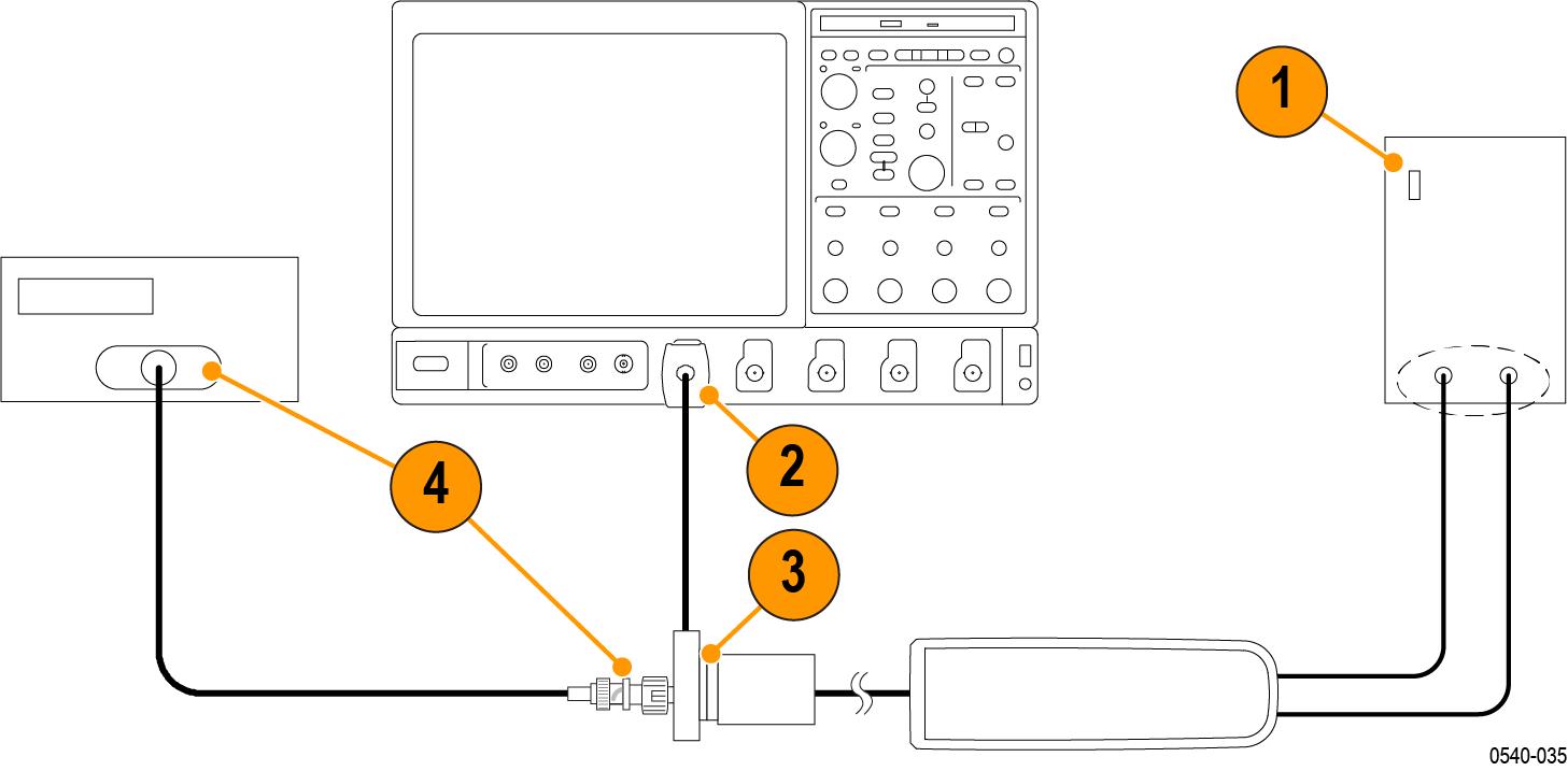
Gain accuracy
The equipment settings for this test differ between probes. Refer to the table for specific settings for the probe that you are testing. See Table 1.
| WARNING:Dangerous voltages will be present on the calibration generator output terminals and connection cables. Always verify that the generator is in the standby mode before you make any connections to the generator. |
- Verify that the generator output is off.
- Connect the probe calibration fixture to any channel (1–4) on the oscilloscope.
- Connect the probe output to the probe calibration fixture.
- Connect the output of the probe calibration fixture to the inputs of the DMM, using coax cables and adapters.
- Set the DMM to AC volts.
- Connect the probe inputs to the front outputs of the generator, using adapters if necessary.
- Set the probe attenuation to the lower (most sensitive) range for the probe that you are adjusting.
- Set the generator square wave output frequency and RMS voltage (main display) to the values shown in the table for the probe that you are adjusting. See Table 1.
Table 1. Adjust gain accuracy equipment settings Probe Generator square wave output Probe output voltage Model Range Voltage (rms) Frequency Expected (rms) Measured (rms) THDP0100 600 V 75 V 100 Hz 750 mV ±15 mV 6000 V 75 V 100 Hz 75 mV ±1.5 mV THDP0200 150 V 25 V 100 Hz 500 mV ±10 mV 1500 V 75 V 100 Hz 150 mV ±3 mV TMDP0200
75 V 20 V 100 Hz 800 mV ±16 mV 750 V 60 V 100 Hz 240 mV ±4.8 mV - Enable the generator output.
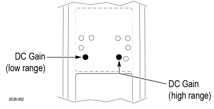
- Adjust the low-range DC gain pot in the probe to ≤2% of the expected output. WARNING:Use only an insulated tool to make the adjustment. Failure to do so presents a potential shock hazard.
- Disable the generator output.
- Set the probe attenuation to the next range and set the generator output voltage to the value shown in the table.
- Enable the generator output and adjust the high-range DC gain pot in the probe to ≤2% of the expected output.
- Disable the generator output.
DC CMRR
| WARNING:Dangerous voltages will be present on the calibration generator output terminals and connection cables. Always verify that the generator is in the standby mode before you make any connections to the generator. |
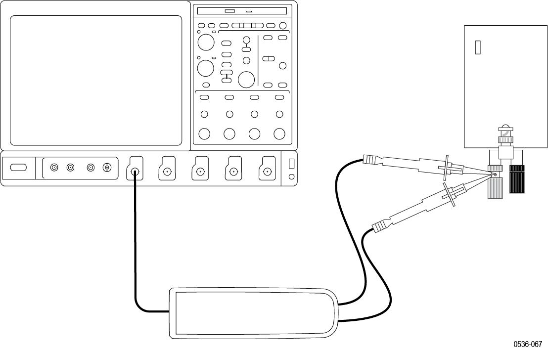
- Verify that the generator output is off.
- Connect both of the probe inputs to the red (+) banana connector on the front output terminals of the generator. Use a BNC-banana adapter if necessary.
- Set the output of the generator to the voltage and frequency listed in the table.
Table 1. DC CMRR test equipment settings Probe Generator output Model Range Voltage (rms) Voltage (p-p) Frequency THDP0100 600 V 353.53 V 1000 V 40 Hz THDP0200 150 V 200 V 566 V 40 Hz TMDP0200 75 V 353.53 V 1000 V 40 Hz - Set the oscilloscope horizontal to 10 ms/div and bandwidth to 5 MHz.
- Set the probe attenuation to the lower (most sensitive) range of the probe.
- Enable the generator output. Set the oscilloscope vertical to display the signal. For a stable display, connect the generator Sense output to another channel and trigger off of that channel.
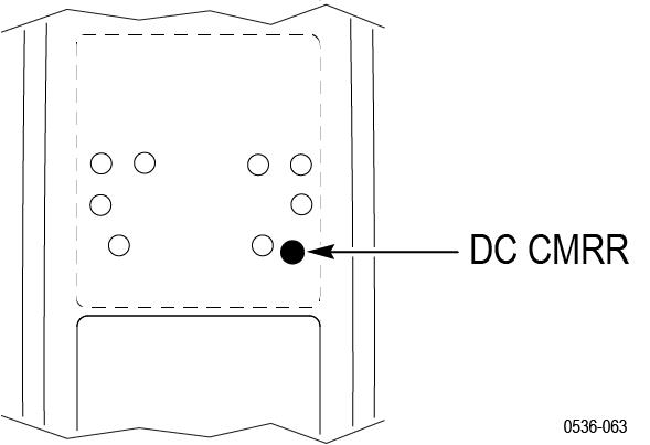
- Using the narrow-bladed tool, adjust the DC CMRR pot in the probe to minimize the amplitude of the waveform displayed on the oscilloscope. Use averaging or hi-res filters to make viewing the 40 Hz signal easier. WARNING:Use only an insulated tool to make the adjustment. Failure to do so presents a potential shock hazard.
- Disable the generator output.
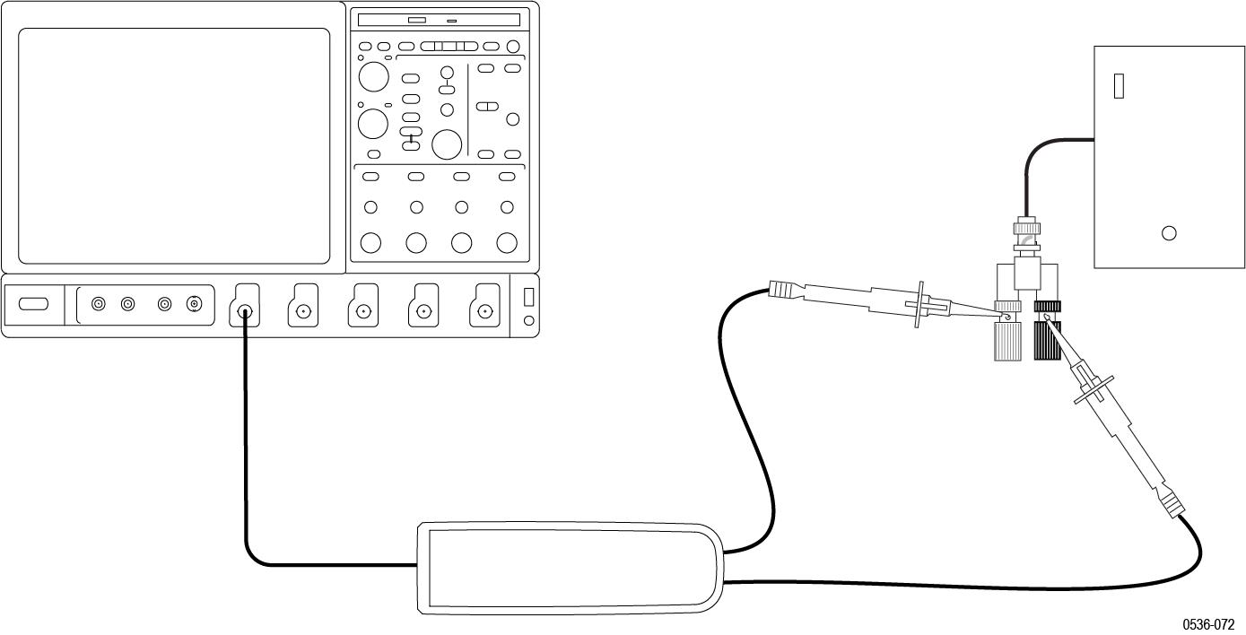
LF compensation
| WARNING:Dangerous voltages will be present on the calibration generator output terminals and connection cables. Always verify that the generator is in the standby mode before you make any connections to the generator. |
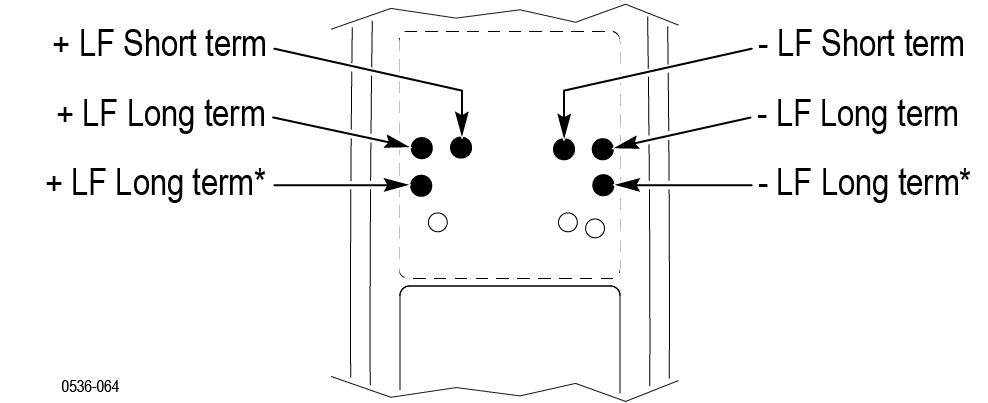
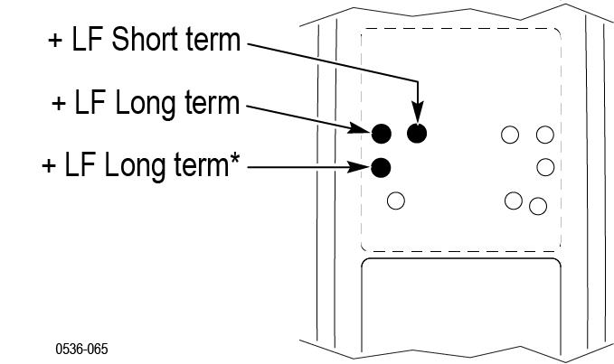
| Note:The TMDP0200 probe only has one long-term +LF adjustment and one long-term –LF adjustment. The other two probe models have two long-term +LF adjustments and two long-term –LF adjustments each. |
- Verify that the generator output is off.
- Connect the probe inputs to the signal output connector on the back of the generator, using adapters if necessary. Connect the red probe lead to the signal, and the black lead to ground.
- Set the probe attenuation to the lower range for the probe that you are adjusting.
- Set the oscilloscope horizontal to 4 μs/div, acq mode = average 16.
- Set the generator fast-rise (rise time waveform) output frequency to 10 kHz.
- Set the generator fast-rise output voltage to 50 Vp-p.
Table 1. LF compensation test equipment settings Probe Generator output Model Range Voltage (p-p) Frequency THDP0100 600 V 50 V 10 kHz THDP0200 150 V 50 V 10 kHz TMDP0200 75 V 50 V 10 kHz - Enable the generator output. Set the oscilloscope vertical to display the signal.
- Make the adjustments in the following order: long-term +LF, long-term +LF*, short-term +LF. (The long-term +LF* adjustment is not used in the TMDP0200 probe.) Repeat this sequence as necessary to optimize the square-wave response. WARNING:Use only an insulated tool to make the adjustment. Failure to do so presents a potential shock hazard.
- Disable the generator output.
- Reverse the probe input leads to the generator.
- Invert the signal and trigger slope on the oscilloscope to display the rising edge of the signal. Adjust the trigger level if necessary.
- Enable the generator output and make the adjustments in the following order: long-term –LF, long-term –LF*, short-term –LF. (The long-term –LF* adjustment is not used in the TMDP0200 probe.) Repeat this sequence as necessary to optimize the square-wave response.
AC CMRR
| WARNING:Dangerous voltages will be present on the calibration generator output terminals and connection cables. Always verify that the generator is in the standby mode before you make any connections to the generator. |
- Verify that the generator output is off.
- Connect both of the probe inputs to the red (+) banana connector on the front output of the generator. Use a BNC-banana adapter if necessary.
- Set the output of the generator to 297 Vp-p (105 Vrms) @100 kHz.
Table 1. AC CMRR test equipment settings Probe Generator output Model Range Voltage (p-p) Frequency THDP0100 600 V 297 V 100 kHz THDP0200 150 V 297 V 100 kHz TMDP0200 75 V 297 V 100 kHz - Set the oscilloscope horizontal to 10 μs/div.
- Set the probe bandwidth to full and the attenuation to the lower range of the probe.
- Enable the generator output. Adjust the oscilloscope vertical to display the signal.
- Make only slight adjustments to only the +LF pots to optimize the CMRR (minimize the signal amplitude). Adjust the pots in the following order: short-term +LF, long-term +LF, long-term +LF*. (The long-term +LF* adjustment is not used in the TMDP0200 probe.) WARNING:Use only an insulated tool to make the adjustment. Failure to do so presents a potential shock hazard.
This completes the adjustment procedures.
Maintenance
Information to isolate possible failures and procedures for maintaining your probe.
Host instrument firmware
Some instruments may require a firmware upgrade to support full functionality of the latest probes that are offered by Tektronix. Instruments with lower versions of firmware may not display all probe controls and indicators on screen, and in some cases may require you to power-cycle the instrument to restore normal instrument operation. If you are having problems with your probe and suspect that you need to upgrade your instrument firmware, go to www.tektronix.com/probe-support to download the latest firmware.
To check the firmware version on Windows-based instruments, from the menu bar, click Help/About TekScope. On Linux-based instruments, press the Utilities button on the front panel.
Error conditions
LEDs do not remain lit
- Disconnect and reconnect the probe to restart the power-on diagnostic sequence.
- Connect the probe to a different channel on the oscilloscope.
- Disconnect the probe from the oscilloscope, power-cycle the oscilloscope, and then reconnect the probe.
- Connect the probe to a different oscilloscope.
If the symptoms remain (they follow the probe), then the probe is defective and must be returned to Tektronix for repair.
Signal display
- Check that the probe accessories that you are using are fully mated.
- Check the probe connection on your circuit.
- Perform a functional check on the probe.
Cleaning
Protect the probe from adverse weather conditions. The probe is not waterproof.
| CAUTION:To prevent damage to the probe, do not expose it to sprays, liquids, or solvents. Avoid getting moisture inside the probe when cleaning the exterior. |
Clean the exterior surfaces of the probe with a dry, lint-free cloth or a soft-bristle brush. If dirt remains, use a soft cloth or swab dampened with a 75% isopropyl alcohol solution. Use only enough solution to dampen the cloth or swab. Do not use abrasive compounds on any part of the probe.
Service
There are no user-serviceable parts in the probes. If your probe requires service, contact your Tektronix service representative or repair center for instructions on returning your probe for repair.
Help us improve our technical documentation. Provide feedback on our TekTalk documentation forum.