联系我们
与泰克代表实时聊天。 工作时间:上午 9:00 - 下午 5:00(太平洋标准时间)。
致电我们
工作时间:上午9:00-下午5:00(太平洋标准时间)
下载
下载手册、产品技术资料、软件等:
反馈
Signal Integrity Modeling - SIM and SIMA
5 Series B MSO, 6 Series B MSO, and 7 Series DPO
SIM sets a new standard for signal integrity modeling and analysis—combining unmatched flexibility with a modern, intuitive user experience.
Define as many simulations as you like, shift reference planes, and explore complex signal paths with ease—all directly from your oscilloscope.
SIM Base (SIM) provides precise de-embedding and embedding of the signal path components to enhance the measurement accuracy, reveal true DUT signal behavior, and design systems that perform reliably in their intended environment. With it, you can move measurement reference planes using virtual test points, rapidly simulate signal path changes, and compensate for the frequency response of cables, probes, and test fixturing, addressing the needs of a wide range of high-speed serial, RF, and power electronics tests.
SIM Advanced (SIMA) includes all the capabilities of SIM, plus advanced equalization tools to address the most challenging high-speed design scenarios. Apply receiver-side equalization techniques such as Continuous Time Linear Equalization (CTLE), Feed Forward Equalization (FFE), and Decision Feedback Equalization (DFE) to open eye diagrams and reduce inter-symbol interference. Apply transmitter equalization, including pre-emphasis and de-emphasis, to model the signal conditioning applied at the source and evaluate its impact across the full transmission path. These techniques enable deeper insight into system performance and help ensure compliance with today’s high-speed interface standards.
Unlike legacy tools that restrict you to just one or two simulations at a time, SIM enables side-by-side comparisons of numerous circuit configurations—unlocking faster, and deeper insight in complex 'what-if' modeling scenarios.
Built on the foundation of Tektronix’ trusted SDLA software, SIM introduces major backend enhancements and a fully modernized interface. Seamlessly integrated into the oscilloscope, it accelerates setup with simplified workflows, touch-optimized controls, and built-in automation—reducing complexity and delivering reliable results quickly for both new and experienced users.
SIMA is expected to be available in early 2026.
Key features
- Physical Model de-embed environment – multi-block
- Simulation Model embed environment – multi-block
- Virtual test points to view signals at impractical probe locations
- Simplified workflows for faster setup
- Time and frequency-domain plots for blocks and test points
- Touch-optimized controls – click and drag blocks and test points
- Save and export filter file results for running within Tektronix automated compliance software and third-party software applications
- Scalable support for numerous simulations and test points
- S-parameter transformations and comparisons for rapid validation
- Receiver equalization – FFE, DFE, and CTLE (requires SIMA)
- Transmitter equalization – add de-emphasis or pre-emphasis (requires SIMA)
- Automatic Tektronix oscilloscope and probe modeling
Applications
- De-embed the effects of cables, fixtures, and probes for system validation
- Simulate the removal of impedance mismatches and explore a range of signal path scenarios to evaluate their impact
- Evaluate signal behavior at various locations along fast or frequency-sensitive signal paths
- Analyze signals in compact IC designs where physical probing is limited by small footprints and dense layouts
- Embed simulation models to evaluate hypothetical or future design scenarios
- Simulate diverse interconnect conditions to evaluate margin, explore design trade-offs, and identify failing scenarios before hardware is built
- Verify channel behavior through time- and frequency-domain plots of S-parameters
- Optimize receiver equalization (DFE, FFE, CTLE) to improve eye openings and meet compliance margins (requires option SIMA)
- Simulate transmitter equalization (pre-/de-emphasis) to optimize performance and reduce hardware iterations (requires option SIMA)
- Correlate real-world measurements with simulation results to validate channel models and build confidence in compliance readiness
- Evaluate signal integrity and generate filters to validate multi-gigabit standards such as USB, PCIe, MIPI, Ethernet, and DDR
Signal Integrity Modeling overview
Modern designs from multi-gigabit serial links to RF modules and sensitive power electronics — all face the same challenge: measurement and interconnect impairments that obscure the true performance of the device. Cables, probes, fixtures, and channel elements introduce reflections, loss, and delay that can dominate over the DUT’s actual behavior. This creates two traps in validation: false failures, where the device appears broken but the issue is the measurement path, and false confidence, where the device looks fine in the lab but collapses in the real system. Addressing these impairments is essential for accurate measurement, meaningful simulation, and reliable system validation.
The rapid increase in signaling speeds and the continued miniaturization of device geometries create significant challenges for next-generation multi-gigabit systems. As form factors shrink and layouts become denser, engineers are often forced to probe signals from non-ideal locations—such as connectors, vias, or other exposed nodes—where impedance discontinuities introduce reflections, loss, and signal distortion. In high-speed designs like DDR or high-density PCBs, these probing limitations can significantly degrade measurement accuracy.
SIM addresses these challenges by enabling precise de-embedding of the measurement circuit—including probes, fixtures, and cables—while accurately accounting for source and load impedances at the transmitter and receiver. You can model and remove these effects using S-parameters or custom circuit blocks, recovering the original waveform at the desired reference plane. This level of correction improves the measurement fidelity and can be the difference between passing and failing compliance tests.
Once the measurement circuit is de-embedded, engineers can explore “what-if” scenarios by embedding a simulation circuit. This may range from a simple 50 Ω termination for transmitter characterization, to a worst-case cable added at the end of a signal path, to a complete backplane or interconnect modeled using S-parameters. These simulations provide valuable insight into system behavior under real-world conditions – helping teams validate design robustness and avoid costly hardware iterations.
Designers increasingly rely on the advanced equalization techniques to compensate for loss and distortion in high-speed channels. In many cases, channel loss can cause eye diagrams to close, masking the true performance of the system. SIM Advanced (SIMA) helps overcome this by providing the receiver equalization tools—including CTLE, FFE, and DFE—that reduce inter-symbol interference (ISI), open closed eyes, and deliver a more accurate view of the receiver performance under realistic operating conditions.
Finally, as transmitter waveforms evolve beyond simple NRZ signaling—toward higher-order schemes and tighter margins—evaluating the impact of transmitter equalization becomes critical. SIMA enables you to apply pre-emphasis or de-emphasis to simulate real-world behavior and optimize system performance across challenging channels.
SIM for the 5, 6, and 7 Series Oscilloscopes provides a modern, oscilloscope-integrated signal integrity modeling environment. Engineers can de-embed measurement artifacts, embed realistic system elements, and apply advanced equalization. Whether validating digital interfaces such as DDR, PCIe, and Ethernet, or modeling RF, high-speed analog, or fast-switching power electronic systems, SIM delivers the capability needed to reveal true signal behavior and avoid costly hardware re-spins.
Enhanced usability and simplified workflows
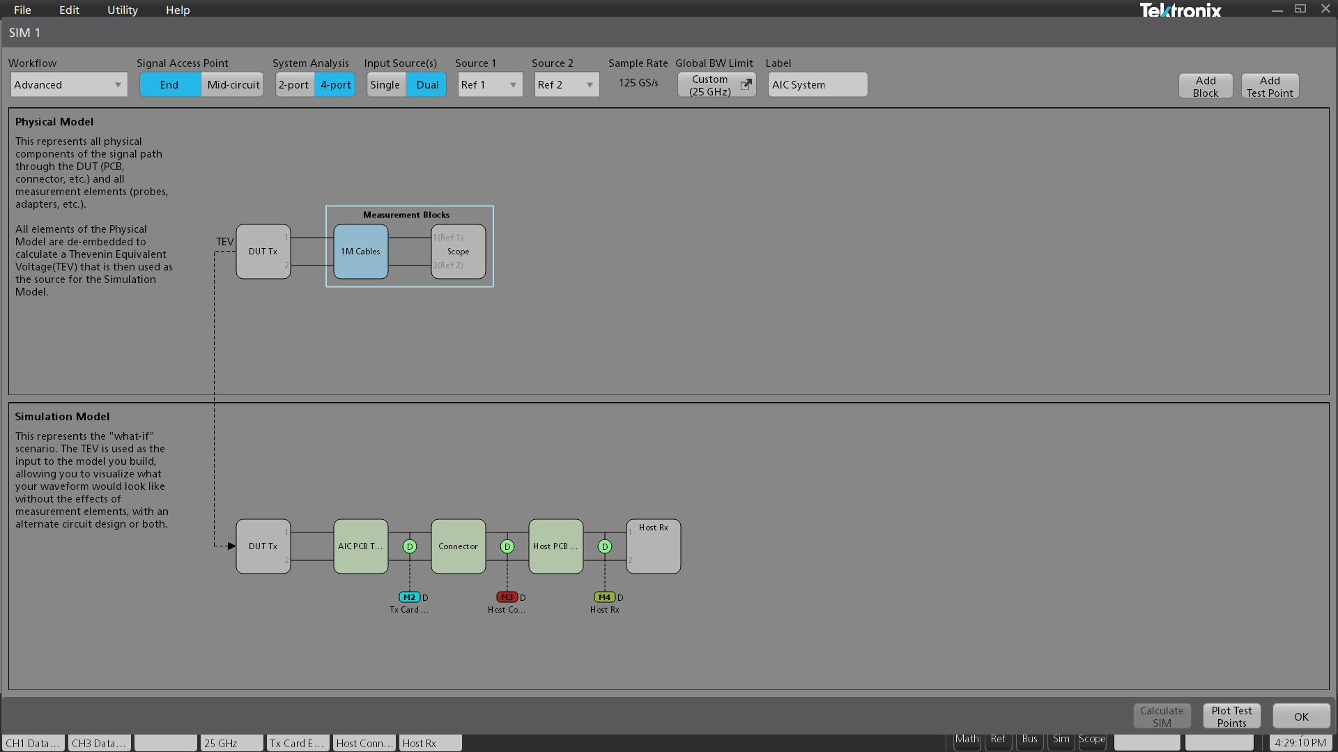
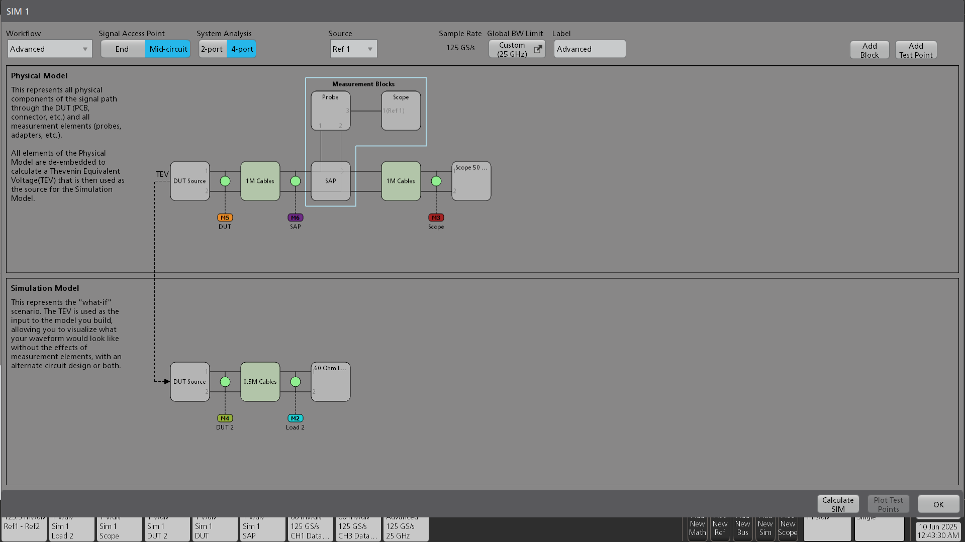
Integrated seamlessly within the TekScope oscilloscope firmware, SIM allows you to quickly visualize the changes to the signal path using both a physical and simulation model. It provides a top-level view that shows all measurement blocks and test points.
The Physical Model represents real-world in-circuit measurement blocks to be de-embedded—such as probes, cables, and fixtures—while the Simulation Model enables “what-if” exploration, showing how the waveform would look when embedded with an alternate circuit, without measurement effects, or both.
The dual-model approach separates real-world measurement effects from hypothetical circuit changes, making it easier to cleanly remove present effects, simulate future scenarios, and confidently optimize system performance.
SIM introduces simplified workflows designed to ease setup for common use cases while supporting more complex modeling when required. Each workflow allows users to focus directly on the task at hand—de-embed, embed, or receiver equalization with SIMA—without requiring a fully defined circuit model. The result is faster setup, easier onboarding, and reduced effort for straightforward tasks. For more demanding scenarios, the Advanced workflow enables combinations of methods within a single simulation. Workflows available include:
- Simple De-embed
- Simple Embed
- Rx Equalization (only available with option SIMA)
- Advanced (for comprehensive modeling)
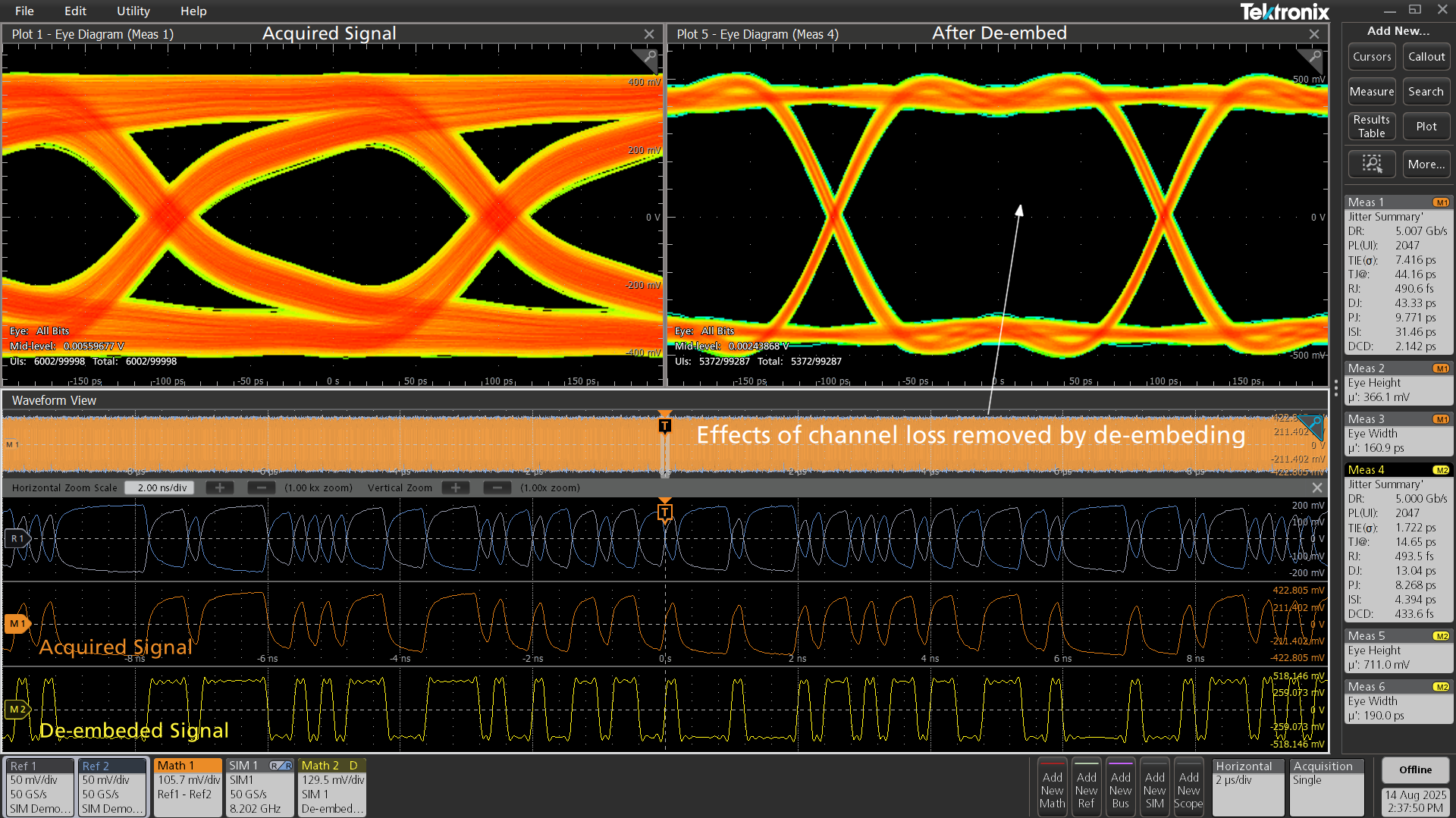
De-embedding the measurement circuit
SIM enables the complete removal of insertion loss, reflections, and cross coupling introduced by the measurement circuit—while accounting for the actual source and load conditions of the system under test. Within SIM’s Physical Model, you can define up to eight blocks representing the measurement circuit to de-embed, such as fixtures, cables, probes, and the oscilloscope itself.
The entire system may be configured for either 2-port or 4-port analysis.
Generic blocks can be described as one of the following:
- Thru
- S-parameters
- RLC Network
- Transmission Line
- Transfer Function
- FIR
- Shunt
Supported S-parameter file types for generic blocks include 2, 4, 6, 8, 12, and 16-port single-ended formats.
Valid input sources may include any channel, math waveform, reference waveform, or “None” for offline analysis.
S-parameter transformation and comparison
SIM includes built-in tool for transforming S-Parameter files to match analysis needs. SIM allows you to flexibly map S-parameter ports to the appropriate locations in the system model. SIM automatically changes the reference impedance to 50 ohms, adjust frequency spacing, and extend the frequency range down to DC through intelligent extrapolation. To ensure confidence in the results, the software enables direct comparison between the original and converted S-parameters using overlaid plot views, making it easy to validate the impact of each transformation before applying the data to your model.
Bandwidth limit control
When de-embedding, it is critical to pay close attention to the signal to noise ratio at higher frequencies. While SIM can automatically determine the bandwidth limit for the de-embed filter, it is often necessary to fine tune the filter. For this reason, SIM provides the ability to set the bandwidth of the source signal, the filter stopband, and attenuation in dB.
Probe and scope blocks
SIM supports probe and scope de-embedding through user-supplied S-parameter files, with an ideal probe option for cases where de-embedding is not required. This approach provides accurate modeling of the measurement path while keeping setup simple. Future enhancements will add automatic scope and probe modeling, beginning in early 2026 for the 7 Series DPO and P77xx, P76xx, and TDP77xx probe families.
Embedding the simulation circuit
View the signal as it would behave in the real-world system—across various scenarios and free from measurement artifacts. The Simulation Model can be defined to visualize your waveform with additional downstream elements embedded.
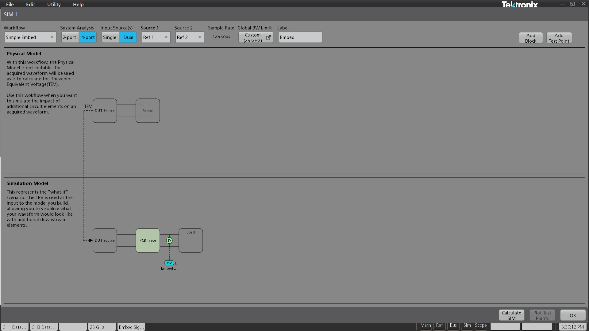
This is easily done in SIM by first defining the Physical Model to de-embed the measurement setup, removing any measurement artifacts, followed by specifying the transmitter (or DUT Source) output impedance. This can be set as a nominal value, two 1-port S-parameter files, or a single 2-port file. The Embed path can then be configured to represent a simple load or a series of cascaded blocks, such as transmission lines and connectors. Like the De-Embed path, the Embed path supports up to eight cascaded blocks.
Complete visibility via virtual test points
Test Points provide insight into signal behavior along complex or inaccessible paths—like compact connectors or embedded traces—by applying FIR-based filtering at virtual circuit locations. Each Test Point generates a dedicated math waveform for easy comparison and analysis.
Within SIM, nearly an unlimited number of test points are available, allowing the maximum flexibility to simulate probing the signal at any point within the system.
Seamlessly manage multiple test points and retain the measurement setups when adjusting locations. You can drag a test point around in the model while keeping already-defined downstream analysis such as jitter measurements, spectrums, eye diagram, etc., significantly enhancing efficiency and prevents measurement error.
Test Points in the de-embed path show the signal with all the loading that is included in the measurement circuit, allowing visibility of the signal with the effects of loading from cables and probes. To visualize the signal without the effects of the measurement circuit, any of the test points along the simulation circuit can be observed.
When computing the test points, SIM automatically removes the delay, so the embedded or de-embedded waveforms are time-aligned. Alternatively, the delay can be preserved by selecting the “Keep Global Delay” option in the Test Point Menu.
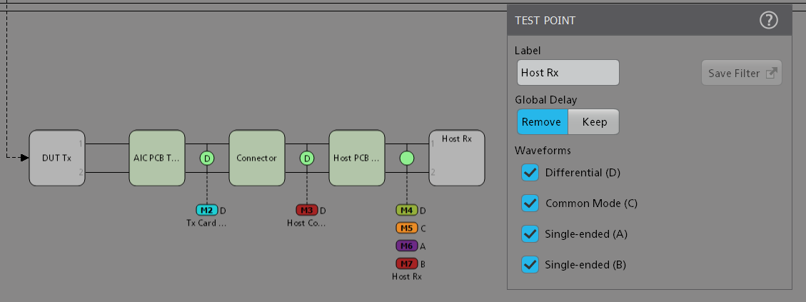
When using SIM Dual Input mode, each leg of the signal is processed independently through the network. In Dual Input mode, the common mode, differential, or individual inputs of the signal can be viewed simultaneously. The effects of reflections, transmission lines, and crosstalk are considered by using all the S-parameter terms throughout the system to build the test point transfer functions.
In addition to supporting all oscilloscope analysis on math waveforms, SIM works seamlessly with Advanced Jitter and Eye Diagram software (option DJA) to measure jitter and timing properties at multiple test points simultaneously—enabling rapid comparison and validation of signal behavior.
Applying equalization (requires SIM Advanced)
At high data rates, signal degradation from loss and interference can close the eye diagram, making analysis difficult. Equalization restores signal clarity, enabling accurate jitter, noise, and standard compliance testing—just as a real receiver would.
Unlike de-embedding, which statically removes known measurement path effects, equalization dynamically compensates for frequency-dependent distortions and adapts to changing channel conditions. Transmitter-side equalization shapes the signal before transmission, while receiver-side equalization recovers signal integrity at the far end. Equalization is required for standards such as USB 3.0, PCIe, DDR5, and high-speed Ethernet.
SIM Advanced provides a robust suite of equalization tools. You can apply transmitter equalization such as pre-emphasis and de-emphasis, and configure user-defined receiver equalization models including CTLE, FFE, and DFE for compliance testing, margin analysis, and debug—even when physical access to the receiver is not possible.
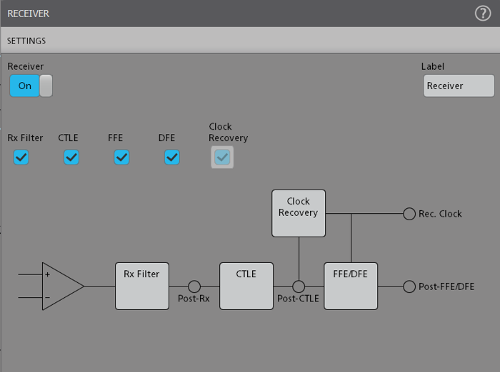
SIMA is expected to be available in early 2026.
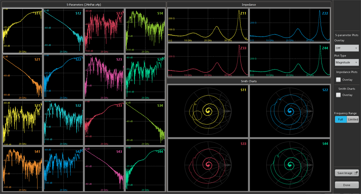
Comprehensive plotting of blocks and test points
SIM makes it easy to move from component-level views—such as S-parameters or impedance—to system-level views of overall signal behavior. By analyzing both blocks and Test Points in the time and frequency domains, SIM provides the visualization needed for deeper insight, validation, and debugging.
Plot types include:
- Magnitude vs. frequency
- Phase vs. frequency
- Impedance as a function of frequency
- Smith Chart
- Step Response
- Impulse Response
Extensive overlay capabilities enable comparison of component S-parameters and overall system behavior.
Specify your frequency range of interest, maximize specific plots for clarity, and export results as PNG, BMP, or JPG files for inclusion in test reports or sharing with colleagues.
Specifications
- Dut Source (transmitter) impedance
- Supports adding pre-emphasis or de-emphasis.
- DUT Source (transmitter) equalization
- Supports adding pre-emphasis or de-emphasis.
- Receiver impedance
- Nominal, two 1-port, or 2-port Touchstone S-parameter matrix, with selectable port assignments
- Receiver equalization type
- Includes CTLE (standard 2nd-order, custom IIR filter, or custom FIR filter up to 12,000 taps max), FFE (up to 100 taps with settable pre/post cursor control and whole-UI or fractional spacing), and DFE (up to 40 taps, settable or adaptive). Taps can be set or trained.
- Receiver equalization training
- Adaptive algorithms (such as MMSE optimization) allow equalizer training using random data, with repetitive patterns recommended for highly distorted signals. Features include pattern detection and export/import of trained coefficients.
- De-Embed path
- Up to eight cascaded blocks consisting of 1-port, 2-port, or 4-port Touchstone S-parameter matrix* (4-port matrix extraction for 6-port, 8-port, 12- port, and 16-port models), with selectable port assignments, single-ended or differential; a custom FIR filter of 12000 taps max, RLC model, or lossless transmission line
- Embed path
- Up to eight cascaded blocks consisting of 1-port, 2-port, or 4-port Touchstone S-parameter matrix* (4-port matrix extraction for 6-port, 8-port, 12- port, and 16-port models), with selectable port assignments, single-ended or differential; a custom FIR filter of 12000 taps max, RLC model, or lossless transmission line
- Waveform record length
- 30 MS typical, less if high number of waveforms or measurement is active simultaneously. DFE waveform is limited to 10 MS (Real-Time only)
- Clock recovery
- 1st- or 2nd-order PLL. Variable loop bandwidth, damping ratio for 2nd-order PLL and clock delay for use with DFE (Real-Time only)
- Touchstone S-parameter matrix format
- Touchstone 1.0 S-parameter matrix format supports both linear and non-uniform frequency spacing. An internal re-sampling function converts non-uniform data to linear spacing. Mixed-mode S-parameters can be included in the Touchstone 1.0 file in various port orderings and are correctly interpreted by SIM
Ordering information
| Description | Product Series | License Type | Option |
|---|---|---|---|
| Signal Integrity Modeling – Base; includes de-embedding, embedding, and core modeling tools (mutually exclusive with SIMA and SIM-UP) | 5 Series B MSO | Node-Locked | 5-SIM |
| 6 Series B MSO | 6-SIM | ||
| 7 Series DPO | 7-SIM | ||
| Signal Integrity Modeling – Advanced; includes de-embedding, embedding, Tx/Rx equalization modeling (pre-emphasis, de-emphasis, CTLE, FFE, DFE), and clock data recovery (CDR) (mutually exclusive with SIM and SIM-UP) | 5 Series B MSO | Node-Locked | 5-SIMA |
| 6 Series B MSO | 6-SIMA | ||
| 7 Series DPO | 7-SIMA |
Upgrade to existing instrument
| Description | Product Series | License Type | Option |
|---|---|---|---|
| Signal Integrity Modeling – Base; includes de-embedding, embedding, and core modeling tools (mutually exclusive with SIMA and SIM-UP) | 5 Series B MSO | Node-Locked | SUP5-SIM |
| Floating | SUP5-SIM-FL | ||
| 6 Series B MSO | Node-Locked | SUP6-SIM | |
| Floating | SUP6-SIM-FL | ||
| 7 Series DPO | Node-Locked | 7-SIM | |
| Floating | 7-SIM-FL | ||
| Signal Integrity Modeling – Advanced; includes de-embedding, embedding, Tx/Rx equalization modeling (pre-emphasis, de-emphasis, CTLE, FFE, DFE), and clock data recovery (CDR) (mutually exclusive with SIM and SIM-UP) | 5 Series B MSO | Node-Locked | SUP5-SIMA |
| Floating | SUP5-SIMA-FL | ||
| 6 Series B MSO | Node-Locked | SUP6-SIMA | |
| Floating | SUP6-SIMA-FL | ||
| 7 Series DPO | Node-Locked | 7-SIMA | |
| Floating | 7-SIMA-FL |
Upgrade existing instrument from SIM Base to SIM Advanced
| Description | Product Series | License Type | Option |
|---|---|---|---|
| Signal Integrity Modeling – Upgrade License from SIM to SIMA to Enable Equalization and CDR (requires existing SIM license and mutually exclusive with SIM and SIMA) | 5 Series B MSO | Node-Locked | SUP5-SIM-UP |
| Floating | SUP5-SIM-UP-FL | ||
| 6 Series B MSO | Node-Locked | SUP6-SIM-UP | |
| Floating | SUP6-SIM-UP-FL | ||
| 7 Series DPO | Node-Locked | 7-SIM-UP | |
| Floating | 7-SIM-UP-FL |
Option software is part of the instrument firmware. Always download and install the latest version of the firmware. User documentation for options is part of the oscilloscope documents. SIM Advanced (SIMA) is expected for release in early 2026.
Recommended software
- DJA
- Advanced Jitter and Eye Diagram Analysis option