When constructing a test system, there might be a need to measure more signals than a single oscilloscope can capture with its available channels. To increase the number of oscilloscope channels in a test system, a common approach is to combine multiple oscilloscopes. Multi-channel measurements find application in various scenarios, such as capturing complex particle physics experiments, measuring numerous power rails, and analyzing 3-phase power converters.
These measurements encompass tasks like detecting crosstalk from a power supply affecting a serial bus, analyzing RF interference, and verifying the integrity of incoming I/O signals. In multi-channel applications or measurement scenarios, maintaining precise synchronization between channels becomes paramount to accurately analyze the timing relationships within the entire system under test.

Figure 1: TekScope PC Analysis Software
When the synchronized capture of many signals is important, there are several options available to synchronize oscilloscopes. Let’s talk about three methods to synchronize a multi-scope measurement system using 5 Series B MSO, 6 Series B MSO, and TekScope PC analysis software (Fig. 1).
- A low-skew synchronization approach using an external source
The most precise synchronization methods rely on a solitary trigger source distributing the trigger signal to multiple oscilloscopes. This is accomplished by utilizing a power splitter (BNC or SMA) that evenly feeds the trigger signal into all instruments. To ensure accurate synchronization, it is essential that the cables connecting the splitter to each instrument are identical in length, ideally using phase matched cables. This approach minimizes the skew resulting from varying propagation delays. By maintaining consistent propagation delays through the cabling and splitters, the instruments can achieve a synchronized trigger condition that closely replicates the channel-to-channel timing of a single oscilloscope.
It is crucial to use a high-quality power splitter to ensure the integrity of the trigger signal. This splitter acts as a balanced voltage divider, linking the 50 Ω trigger source to 50 Ω cables, which are then connected to a 50 Ω input on the oscilloscope. The splitter will reduce the amplitude of the trigger signal being applied to each oscilloscope, so it is important to account for this when setting the trigger level.
It is essential to be mindful of the specifications of your splitter and the requirements of the trigger signal. For instance, for driving the auxiliary trigger input of a 5 or 6 Series B MSO, a signal greater than 500 mV is optimal. Supplying larger trigger signals improves the oscilloscope's trigger system response and stability, leading to better skew results. Therefore, using an appropriate splitter and ensuring an adequately sized trigger signal will maintain excellent trigger signal integrity.
- A probe-based synchronization approach
If an external trigger source is unavailable or unable to drive a 50 ohm splitter, an alternative method for achieving synchronization involves probing the same trigger source on each oscilloscope. While this approach provides excellent timing accuracy, it comes at the cost of sacrificing one channel on each scope. However, the skew caused by differences in propagation delay remains well within the oscilloscope's deskew settings.
To minimize overall skew, using an active probe like the Tektronix TAP4000 is recommended (See Fig.2). This probe offers a pulse rise time of less than 115 ps, making it ideal for reducing trigger jitter. Additionally, the TAP4000 probe boasts an input capacitance as low as 0.8 pf. Keep in mind that this capacitance is additive for each probe, so the circuit must handle the additional loading.

Figure 2: The Tektronix TAP4000 Single-Ended Low Voltage Probe
To implement the probe-based synchronization method between two scopes, connect an oscilloscope probe (preferably a TAP4000) to a channel of each scope. Probe the same signal using the same type of probe tip with identical lengths on both probes. It is essential for the trigger signal being probed to have a relatively fast rise time (around 50-100 psec). On the scopes, enable a simple edge trigger with the trigger level set to mid-scale on each scope. Note that any differences in the trigger level may introduce additional skew.
Depending on the trigger source used, it should be possible to achieve an overall skew in the range of tens of picoseconds with this approach. This method offers a viable solution for synchronization when an external trigger source is unavailable or impractical for the specific trigger requirements.
- A simplified synchronization approach for applications with less stringent timing requirements
When a multi-oscilloscope system doesn't demand exceptionally low skew, it grants greater flexibility in the setup.
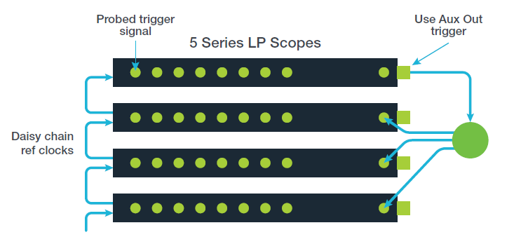
Figure 3: the aux trigger out from the master oscilloscope serves as the source to feed other scopes through a splitter
In the configuration above (Fig.3), the aux trigger out from the master oscilloscope serves as the source to feed other scopes through a splitter. In the 5 or 6 Series B MSO, there exists a nominal 900 ns skew between a trigger event and the Aux Out signal. By utilizing a splitter along with matched cables, any additional skew to the remaining scopes is minimized.
If the record length is sufficiently long, a trigger delay setting in the horizontal badge settings can be applied to rectify the skew between the trigger and Aux Out. This setup offers the advantage of enabling any channel on the master scope to function as a trigger source, freeing up all of the channels on the remaining oscilloscopes for signal acquisition.


When ensuring the synchronized capture of numerous signals is crucial, these options can help with synchronizing oscilloscopes. For more detail on these steps, and how to use TekScope PC, download the technical brief – How to Synchronize 4/5/6 Series MSO Oscilloscopes for Higher Channel Count.