
本应用指南介绍了同步多台示波器的方法,在阅 读本应用指南的过程中,您将了解到以下内容:
- 同步示波器时需要考虑的事项
- 示波器之间时序误差的成因
- 推荐的同步方法
- 多示波器软件的设置
本应用指南以泰克 4,5 和 6 系列 MSO 为例,说 明了多示波器同步的程序和原理。4,5 和 6 系列 MSO 支持任意型号示波器之间的同步,从而实现 更多通道的同步采集系统。
通道数量为何要求超过 4 个?
4 系列 B MSO 示波器是同系列产品中首个推出 6 通道 的型号,可满足用户多种测试应用场景。可应用于复杂 粒子物理实验的捕获、多个电源轨的测量、三相电源转 换器的分析等场景。测量可以包括串行总线中出现的电 源串扰、分析射频干扰、同步观测输入 / 输出信号的传 输等等。
人们也会通过同步多台示波器能够测量更多通道。在 多通道应用或测量场景中,为了精确分析整个被测系统 的时序关系,保持通道间的精确同步非常重要。
多示波器测量的考虑因素
软件
对于多示波器测量系统,软件可以发挥关键的作用。从 最基本的层面来说,软件需要整合多台仪器的数据,并 由软件进行仪器的触发和采集设置。软件还可提供组 合波形的显示和分析功能。
另外,软件可以帮助完成相差校正。虽然用户可以通过 编写自定义软件来完成这些任务,但比起繁琐的程序开 发过程,TekScope PC 分析软件直接提供这些功能,可 以更加快捷高效地完成复杂的设置,让用户更专注于 测试本身。在本应用指南中,TekScope PC 软件将用于 多示波器控制和采集,后面的章节介绍了该软件的使 用方法。
系统配置
考虑测试系统的同步方法时,理解各种同步策略以及 通道间容许的时序误差量非常重要。不同的线缆连接、 触发和延迟补偿方法会对时序误差产生重大影响。示 波器内外部(即线缆和探头)的通道延迟差异会导致通 道之间的时序误差或“相差”。在决定同步策略时,首 先需要回答几个关键问题。测试系统输入通道间可以容 许多大相差?是所有的输入通道都需要满足严格的相 差容许,还是只有部分通道需要?比如机电或人机应用 的测量,零点几毫秒是可以容许的。然而,高速电子系 统的测量就需要更高的同步性。
In order to better understand the tradeoffs in configuring a solution, it helps to understand the sources of timing error in a multi-instrument system.
时序误差的来源
为了更好地理解时序误差的来源,可将其分为四种类型:
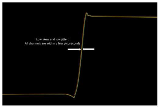
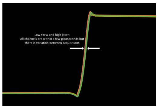
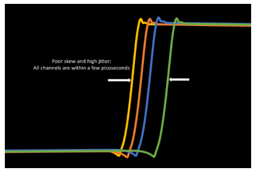
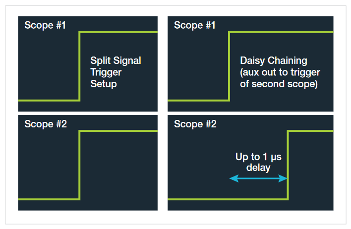
- 1. 触发抖动
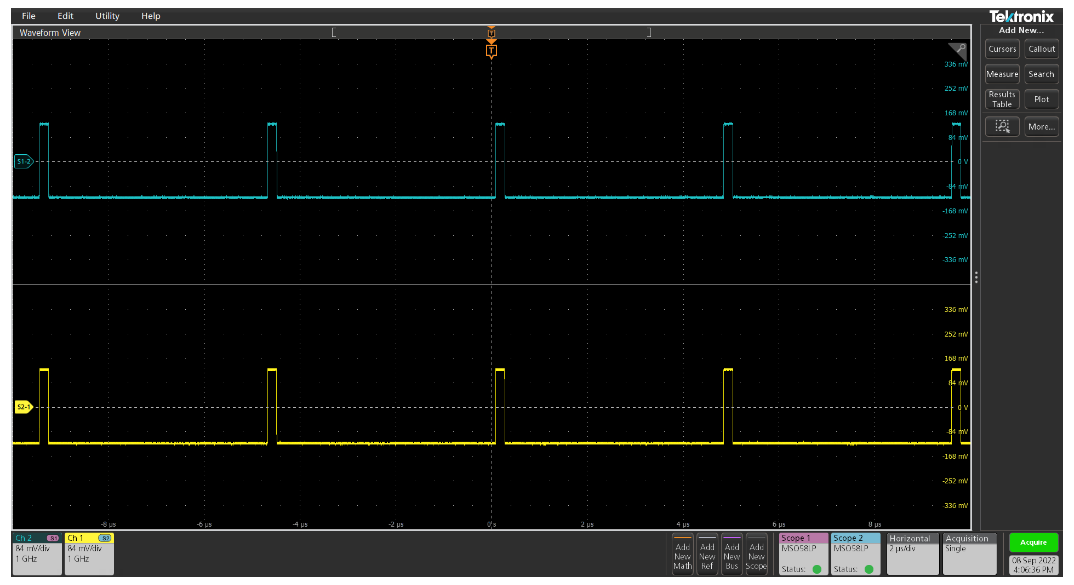
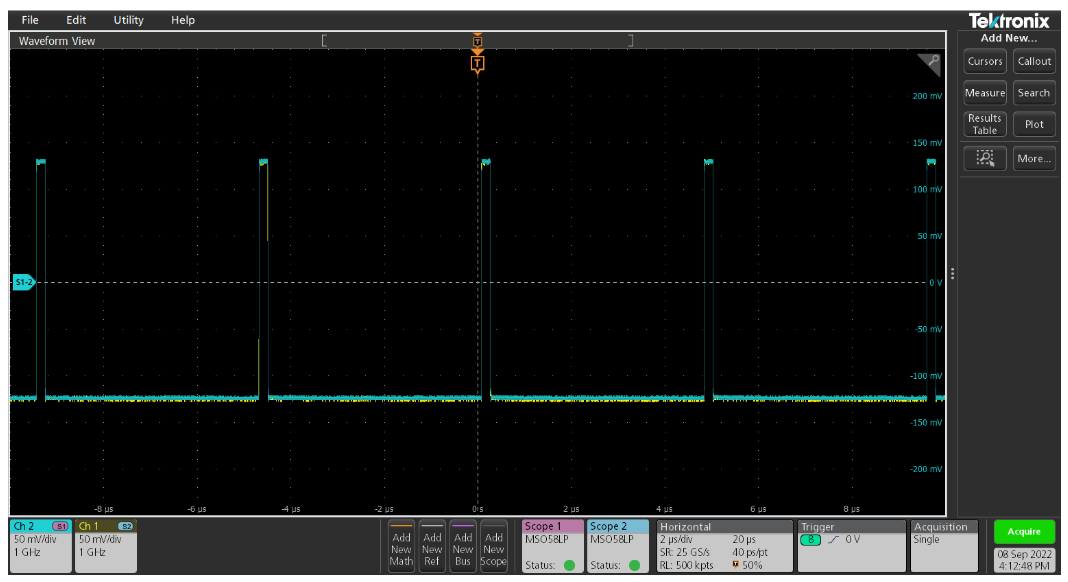
触发抖动是时序误差的逐次采集变化。将示波器设置 为无限余晖并观测一个与触发同步的信号时,可以看到 这一现象。如图 1a 与图 1c 的差异所示。使用外部触发 源或用探头的 4、5、6 系列 MSO 输入通道,抖动将小 于 10 ps。若采用辅助触发输入,会增加超过 200 ps 的 抖动。 - 2. 示波器通道间的相差
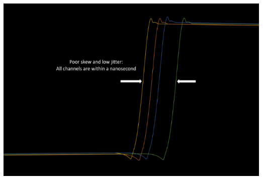
4、5 和 6 系列 MSO 规格书载明,使用探头时,模拟通 道间的延迟将小于 100ps。 - 3. 各示波器外部触发器或探头的电缆传播延迟产生的
相差
使用外部触发器和功分器时,电缆长度的任何差异都会 导致约 70ps/cm 的相差。如果每台示波器上使用相同 的模拟探头作为触发源,相差应小于 100ps。如图 1b 所示。 - 4. 触发事件与辅助触发输出信号之间的相差。
当被触发示波器的辅助输出端口指定为触发输出信号 时,存在 1 µs 的固有相差。如不加以校正,对于大多 数应用场景来说,该相差量可能过大。如果记录长度 足够长,则可使用预触发延迟进行校正。如图 2 右侧 所示。
1. 使用外部源的低相差同步方法
最 精确 的同步技术是 使 用单个 触 发 源,通 过 功 分 器 (BNC 或 SMA)将触发信号分离,将同一信号馈送到 多台示波器,如图 3 所示。连接分离器和所有仪器的 应该为相同长度的同类电缆(最好是相位匹配电缆), 这样可以减小由于不同传播延迟导致的相差。
关于功分器
为了维持触发信号的完整性,我们采用高质量的功分 器。该分离器充当平衡分压器,将 50Ω 触发源连接到 50Ω 电缆,再连接到示波器的 50Ω 输入。功分器(如 图 4 所示)将电压分配到四条支路上,从而 5V 峰值触 发器能为每条支路提供 1.25 V 的电压。请注意功分器 的规格和触发信号要求。驱动 4,5,6 系列 MSO 的辅 助触发输入的信号电平最好大于 500 mV。提供的触发 信号越大,示波器的触发系统响应越好,越稳定,相差 结果就越好。
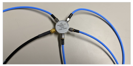
图 3 和图 4 所示是泰克推荐的同步配件:SMA 高带宽 4 路功 率分离器(泰克部件 编号:174-6214-00)和 4 根匹配的 SMA 电缆(泰克部件编号:174-6212-00)。 所示电缆在 ps 内匹配,以控制相差。
同步参考时钟
通过高保真 10 MHz 参考时钟锁定示波器的采样器也 是非常重要的。这样可以消除时基之间的长期漂移效 应,最大限度地减少了在跨度较大(>2ms)的通道间测 量中的差量时间精度误差。
同步参考时钟有两种方法:
- 1. 最好的方法是使用高稳定性的外部时钟,并使用一 个功分器来馈送每个参考时钟输入。这与用于分离 触发信号的方法类似,如图 3 和图 4 所示。
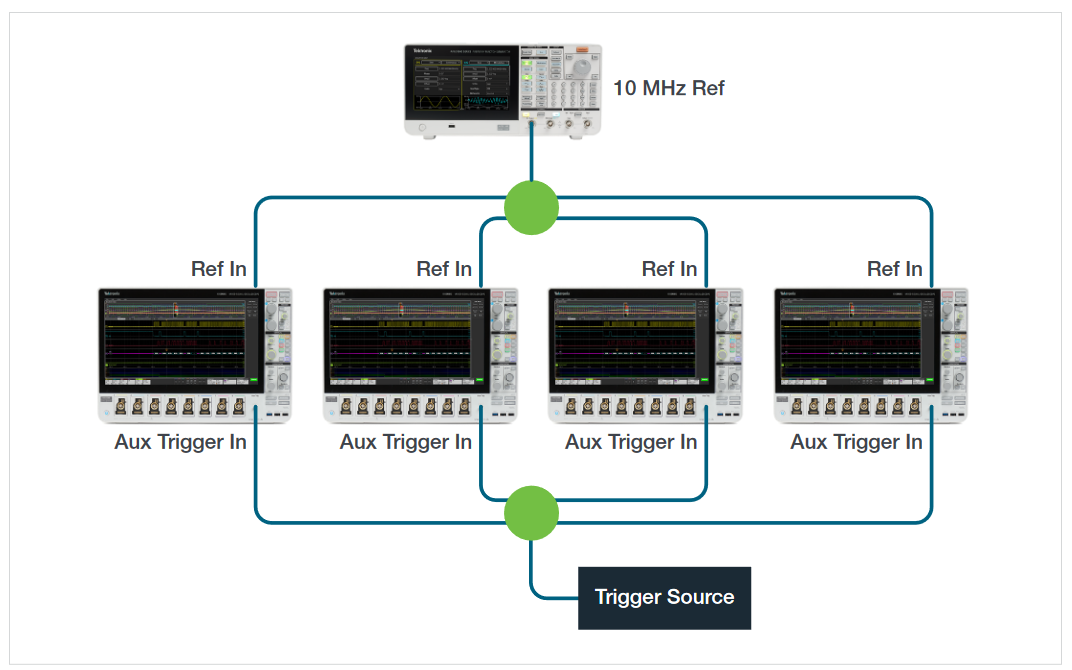
- 2. 另一种方法是使用一台示波器的内部参考时钟,并 将其馈送到下一台示波器,如图 5 所示。而该示波器 的辅助输出可为串联的下一台示波器的参考输入进 行馈送,依此类推。这种方法适用于内部参考时基精 度满足要求的情况。
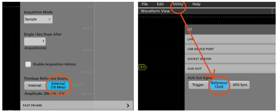
无论哪种情况,对于接收 10 MHz 参考时钟的仪器,参 考时钟源均应设置为外部。双 击 4,5,6 系列 MSO 上的 “Acquisition”(采 集)标 志,可找 到该设 置,如 图 6 左侧所示。一旦发射和接收示波器配置并同步,时基参 考源应显示绿色“Locked”(已锁定)指示。
在输出参考时钟的仪器上,必须进入“Utility”(实用 程序)菜单 ,“Aux Out”(辅助输出)选择参考时钟, 将参考时钟指定为辅助输出 ,如图 6 右侧所示。

使用 TekScope PC‒ 多示波器客户端和相差校正工具
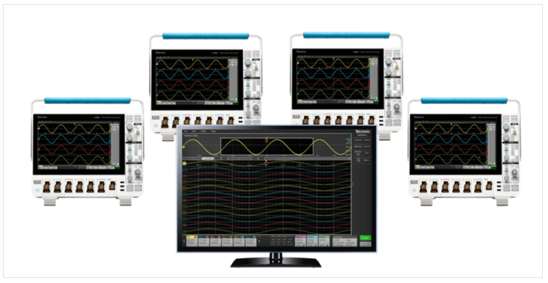
TekScope ™ PC 分析软件是泰克提供的一款应用程序,非常适合多示波器配置。该软件的操作方式与 �/�/� 系列 MSO 用户界面相同,但在 Windows 电脑上远程运行。使用 TekScope 可以连接多台示波器,并在单个界面上显示 所有波形,就和在单台示波器上运行一样。该软件还能将所有连接示波器的全部数据保存在一个文件里。
配置 TekScope PC 用于多示波器应用
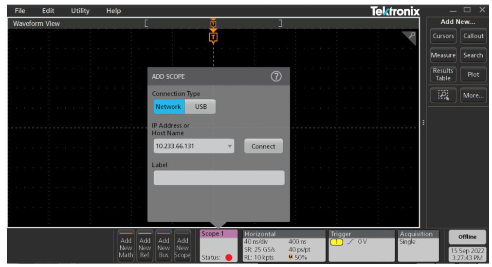
连接 4,5 或 6 系列 MSO 示波器非常简单。单击“Add New Scope”(添加示波器)标志,将添加一台新示波器。 双击示波器标志,输入 IP 地址,然后连接,如图 8 所示。
使用 TekScope 对多示波器系统进行相差校正
相差校正过程包括测量及消除不同示波器通道之间的相差。
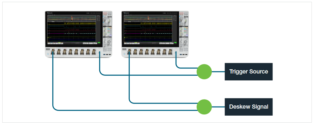
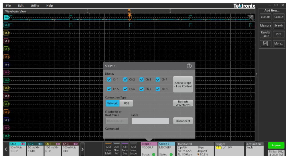
需要将非触发信号的时钟信号接入到两个待校正相差的通道上,如图 10 所示。该信号应具有快速上升时间(例如 50 ps)。使用 TekScope PC 一次连接两台示波器。选择一个通道作为参考,如图 11 所示。
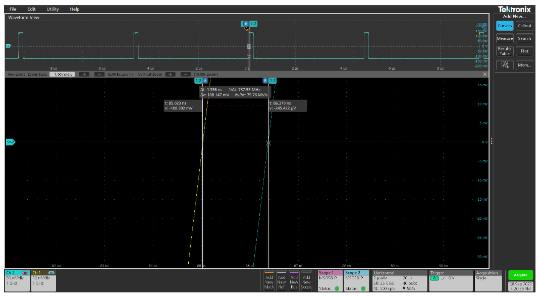
下一步是叠加显示两个通道,如图 12 所示。然后,放大信号的前缘,这样就可以使用光标来测量差量时间,如图 13 所示。
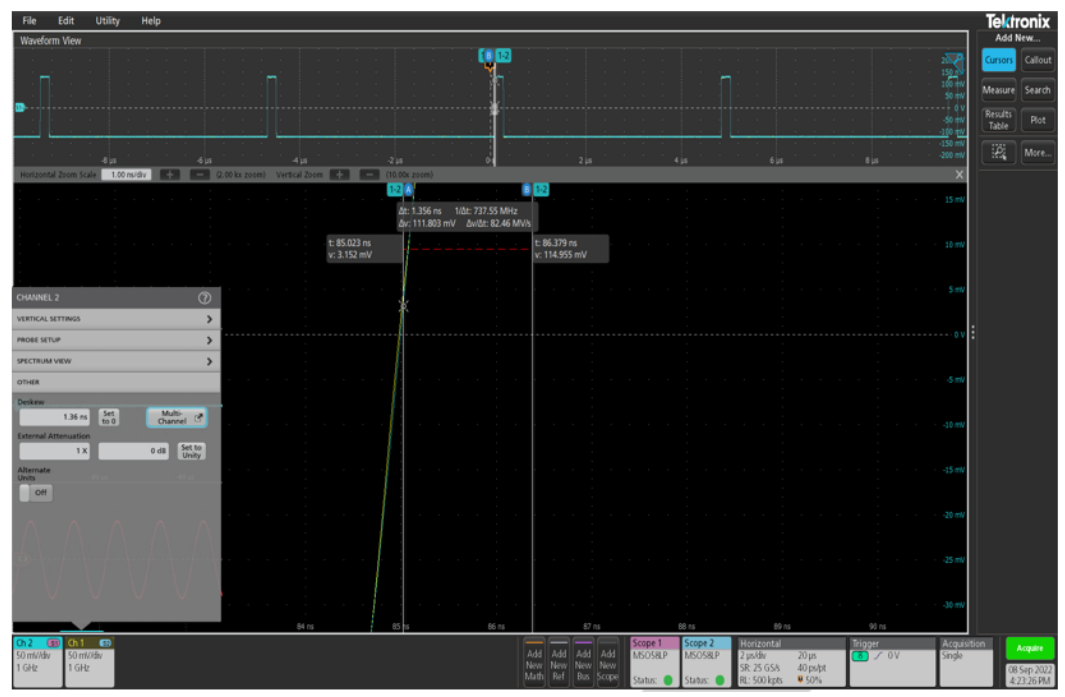
现在需要消除通道间存在的相差。双击该通道的垂直菜单。在“Deskew”(相差校正)设置中输入测得的差量时间。 如图 14 所示。所有通道都必须重复以上操作。
总结
本技术简介介绍了使用 4,5 和 6 系列 MSO 示波器和 TekScope PC 分析软件同步多示波器测量系统的方法。4,5 和 6 系列 MSO 支持任意型号示波器之间的同步,从而实现更多通道的同步采集系统。