联系我们
与泰克代表实时聊天。 工作时间:上午 9:00 - 下午 5:00(太平洋标准时间)。
致电我们
工作时间:上午9:00-下午5:00(太平洋标准时间)
下载
下载手册、产品技术资料、软件等:
反馈
RM3 Rackmount Kit Instructions
This document supports installing the Tektronix 3 Series MDO instrument in a rackmount kit to fit in a standard 19-inch equipment rack.
此手册适用于:
MDO32, MDO34, RM3
相关产品信息
下载即代表您同意手册下载协议的条款和条件。
手册下载协议
注意:从本网站下载任何文档之前,请认真阅读以下条件和条款。 如果从泰克网站上下载手册,即表示您同意以下条件和条款:
当前支持的产品的手册:
泰克在此向泰克仪器的所有者授予权限和许可,可从此网站上下载和复制手册供其自己内部或个人使用。 除非经过泰克公司书面专门授权,当前支持产品的手册不得复制用于发行。
泰克手册可能会被更新以反映产品制造寿命过程中所做的更改。 因此,任何给定产品都可能存在多个手册版本。 请小心使用,确保为特定的产品序列号获取正确的手册版本。
不再支持的产品的手册:
对于不再适于长期支持的测量产品,泰克无法提供手册。 泰克特此向他人授予权限和许可,对于 (a) 拥有泰克部件号,并且 (b) 用于泰克不再支持的测量产品,可以复制和发行泰克任何测量产品手册的副本,包括用户手册、操作手册、维修手册等等。
泰克手册可能会被更新以反映产品制造寿命过程中所做的更改。 因此,任何给定产品都可能存在多个手册版本。 请小心使用,确保为特定的产品序列号获取正确的手册版本。
此授权和许可不适用于泰克仍在提供的任何手册和其他出版物,或者用于视频制作产品或彩色打印机产品的任何手册和其他出版物。
免责条款:
对于非泰克提供的、或者按照上述授权和许可复制或发行的任何测量产品手册或其他出版物,泰克对于其中所含任何信息、文字、图形、原理图、部件清单或其他材料的准确性和完整性不做保证。
泰克可能会随时更改本网站或其产品的内容而不事先通知。
责任限制:
对于使用按照上述授权和许可制作或发行的任何测量产品手册或其他出版物所造成的任何损害,包括但不限于利润损失、业务中断或侵犯知识产权,泰克不应承担责任。
Read Online
Important safety information
This manual contains information and warnings that must be followed by the user for safe operation and to keep the product in a safe condition.
To safely perform service on this product, see the Service safety summary that follows the General safety summary.
Service safety summary
The Service safety summary section contains additional information required to safely perform service on the product. Only qualified personnel should perform service procedures. Read this Service safety summary and the General safety summary before performing any service procedures.
To avoid electric shock
Do not touch exposed connections.
Do not service alone
Do not perform internal service or adjustments of this product unless another person capable of rendering first aid and resuscitation is present.
Disconnect power
To avoid electric shock, switch off the product power and disconnect the power cord from the mains power before removing any covers or panels, or opening the case for servicing.
Use care when servicing with power on
Dangerous voltages or currents may exist in this product. Disconnect power, remove battery (if applicable), and disconnect test leads before removing protective panels, soldering, or replacing components.
Verify safety after repair
Always recheck ground continuity and mains dielectric strength after performing a repair.
Terms in this manual
These terms may appear in this manual:
 | WARNING:Warning statements identify conditions or practices that could result in injury or loss of life. |
| CAUTION:Caution statements identify conditions or practices that could result in damage to this product or other property. |
Kit description
This document supports Tektronix 3 Series MDO instrument. The rackmount kit is a collection of parts that, once installed, configure the instrument for mounting into a standard 19-inch equipment rack.
Products
This rackmount kit supports the 3 Series MDO instruments.
Minimum tool and equipment list
| Required tools and equipment | Part number |
|---|---|
| Screwdriver, Phillips, #2 | Standard tool |
| Wrench, 3/8" | Standard tool |
| Screwdriver, T-20 Torx | Standard tool |
| Screwdriver, T-10 Torx | Standard tool |
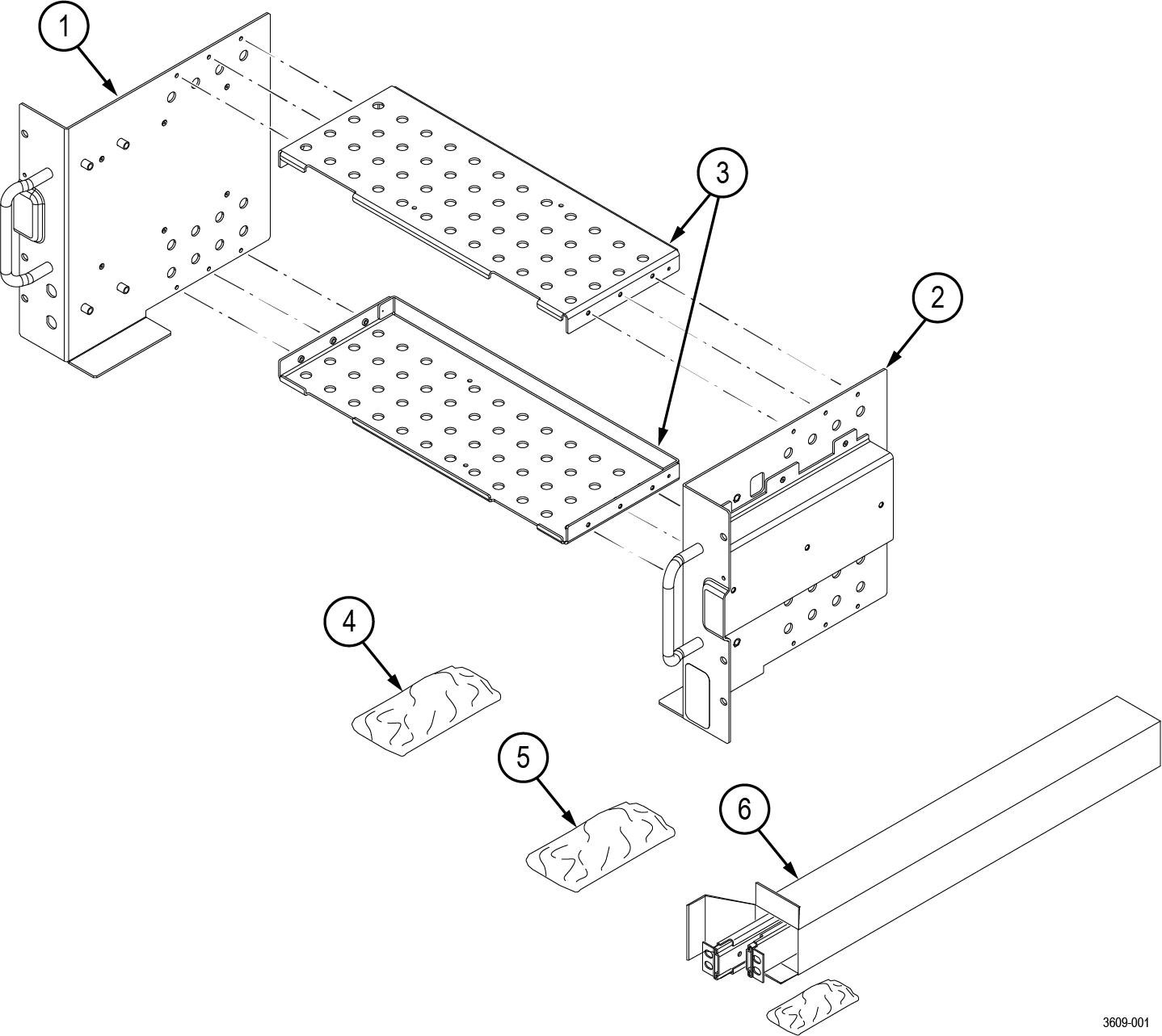
Kit parts lists
The following tables list the parts for the RM3 rack mount kit; not all of the parts will be needed for your instrument setup.
| Item | Quantity | Part number | Description |
|---|---|---|---|
| ----- | 1 each | 071-3609-xx | RM3 RACK MOUNT KIT INSTRUCTIONS |
| 1 | 1 | 407-6184-xx | BRACKET, ASSEMBLY, LEFT RACKMOUNT KIT |
| 2 | 1 | 407-6183-xx | BRACKET, ASSEMBLY, RIGHT RACKMOUNT KIT |
| 3 | 2 | 407-6182-xx | BRACKET, TOP AND BOTTOM RACKMOUNT KIT |
| 4 | 1 | 016-2142-xx | KIT, HARDWARE RACKMOUNT KIT This kit includes the hardware required to assemble the rackmount kit and attach it to the instrument. See Table 2 for the hardware list |
| 5 | 1 | 016-2116-xx | KIT, HARDWARE RACKMOUNT KIT This kit includes the hardware required to mount the assembled instrument and rack kit to the instrument rack. See Table 3 for the hardware list |
| 6 | 1 | 351-1095-xx | SLIDE ASSY; PAIR, W/STD HARDWARE KIT AND REAR BRACKET, SAFETY CONTROLLED |
| Item | Quantity | Part number | Description |
|---|---|---|---|
| H1 | 12 | 211-1584-xx | SCREW, MACHINE, M3X0.5X6MM PAN HEAD, TORX T10 |
| H2 | 8 | 211-1694-xx | SCREW, MACHINE, M4X0.7X16MM PAN HEAD, TORX T20 |
| H3 | 6 | 211-1695-xx | SCREW, MACHINE, M4X0.7X6MM PAN HEAD, TORX T20 |
| Item | Quantity | Part number | Description |
|---|---|---|---|
| H4 | 14 | 210-0833-xx | WASHER, RECESSED; 0.42 ID X 0.112 THK, STL NI PLATED, 0.588 OD |
| H5 | 14 | 210-1061-xx | WASHER, FLAT; 0.203 ID X 0.625 OD X 0.062, ZINC PLATED STEEL |
| H6 | 14 | 210-1548-xx | WASHER, FLAT 12 OD X 6.4 ID X 1.6THK |
| H7 | 14 | 211-1218-xx | SCREW, M6 X 16MM OVAL HEAD, PHILLIPS |
| H8 | 14 | 211-1219-xx | SCREW, M5 X 16MM OVAL HEAD, PHILLIPS |
| H9 | 14 | 212-0591-xx | SCREW, MACHINE; 10-32X.750 OVAL HEAD, POZI |
| H10 | 14 | 213-0199-xx | SCREW, MACHINE; 12-24 X 0.75, OVH, STL NP, POZ |
Warranted characteristics
When the instrument is installed according to the instructions in this document, the rackmounted instrument meets all warranted requirements listed in the instrument specification. Instruments mounted using methods other than those described in these instructions might not meet their warranted requirements.
For tables of the warranted characteristics, see Specifications in the specification and performance verification manual that applies to your instrument model.
| CAUTION:The rack is more susceptible to tipping when the instrument is installed. To prevent the rack from tipping, ensure that the rack is stable before accessing rear panel of the instrument. Do not leave the instrument extended in the rack. |
The ambient temperature inside the instrument rack will vary depending on the location of the instrument within the instrument rack. Tektronix recommends that you measure the ambient temperature in the desired rack location before you install the instrument to ensure the operating temperature does not exceed the rated ambient temperature limit. If necessary, refer to the Environmental Specifications in your product documentation for the operating temperature limits.
| CAUTION:The instrument might be damaged due to overheating. When installing multiple instruments in an instrument rack, the ambient temperature may go up. You assume the responsibility to provide adequate cooling to meet the ambient temperature requirements listed in the specifications. |
Clearance requirements
The rack in which the individual instrument is mounted must provide the following clearance requirements:
- At least 266 mm (10.5 in) of vertical space or 6 RU (rack units) of vertical space
- A minimum width of 488 mm (19.2 in) between the left- and right-front rails in the rack. If possible, consider allowing at least 50.8 mm (2.0 in) on the right side and rear of the instrument for adequate airflow.
- A minimum inside depth of at least 254 mm (10 in) depth (from rack mounting ear to back of instrument). Airflow enters from the back of the instrument and exits on the right of the instrument when viewed from the front.
| CAUTION:Adhering to these requirements mounts the rack-adapted instrument with enough clearance for air circulation and accommodation of the power cord and mounting hardware. Failure to provide these clearances can result in overheating and can cause the instrument to operate improperly or fail. |
RM3 Installation instructions
These instructions are for qualified service personnel who are familiar with servicing the product. If you need further details for disassembling or reassembling the product, refer to the appropriate product manual. Contact your nearest Tektronix, Inc., Service Center or Tektronix Factory Service for installation assistance.
Assemble the rack mount on the instrument
Item numbers referenced in the assembly steps refer to the parts list in Table 1 and Table 2.
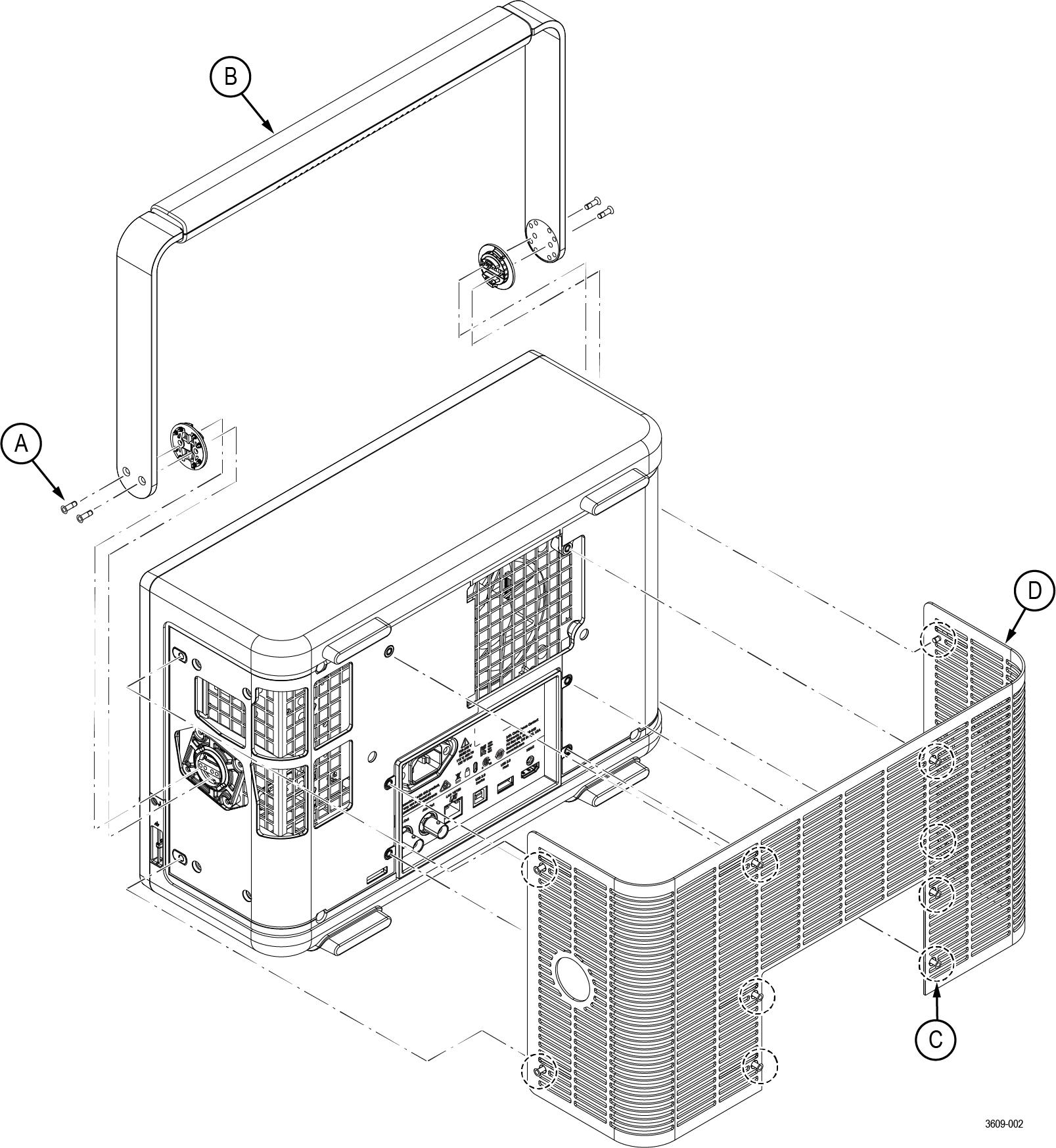
- Remove the instrument handle, hubs, and grill. Save the parts and hardware for future use.
- Remove the four TORX T10 screws from the handle.
- Remove the handle and the two handle hub couplers from the instrument.
- Remove the ten TORX T10 screws from the grill.
- Remove the grill from the back of instrument.
Figure 1. Prepare the instrument 
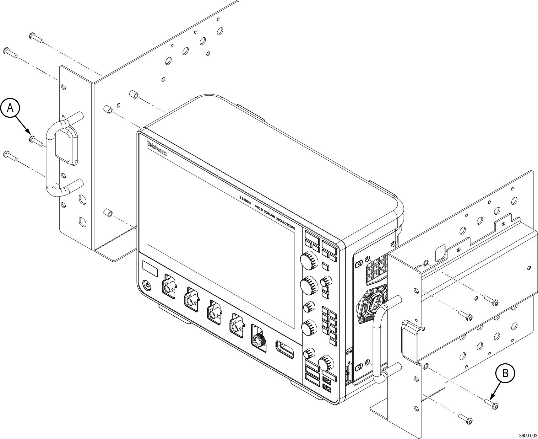
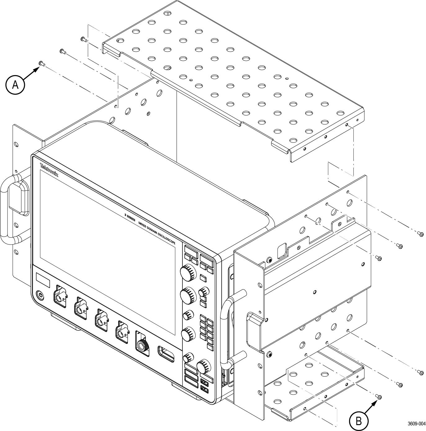
- Install the left and right mounting plates.
- Use four TORX T20 screws (item H2) to install the left mounting plate (item 1) to the instrument.
- Use four TORX T20 screws (item H2) to install the right mounting plate (item 2) to the instrument.
Figure 2. Mounting plate installation - Install the top and bottom support plates.
- Use six TORX T10 screws (item H1) to install the top support plate (item 3) to the mounting plates.
- Use six TORX T10 screws (item H1) to install the bottom support plate (item 3) to the mounting plates.
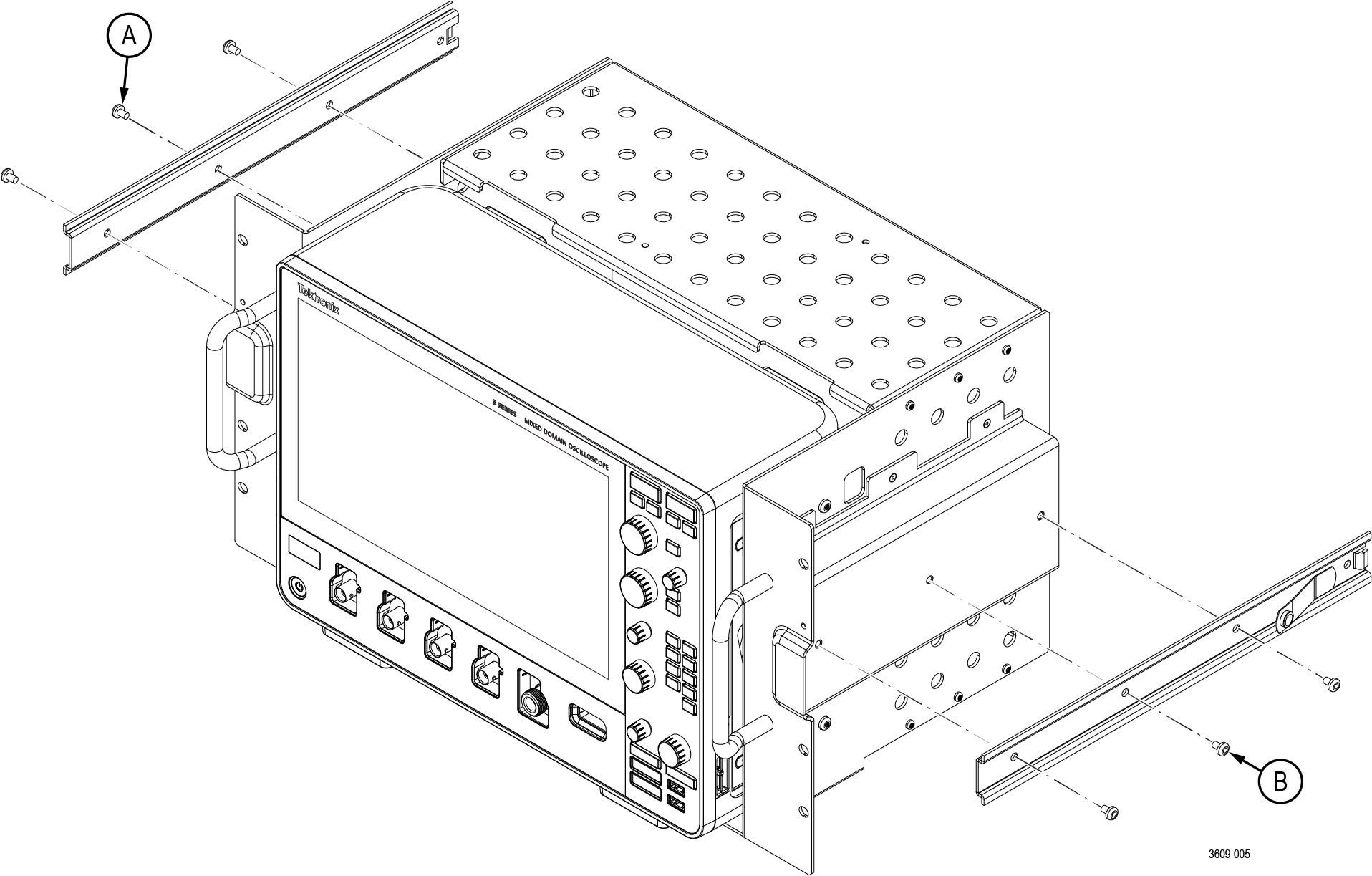
Figure 3. Support plate installation - Install the left-side and right-side slide mounts.
- Use three TORX T20 screws (item H3) to install the instrument-side portion of the slide (item 6) to the right mounting plate.
- Use three TORX T20 screws (item H3) to install the instrument-side portion of the slide (item 6) to the left mounting plate.
Figure 4. Slide mount installation
Install the instrument into the rack
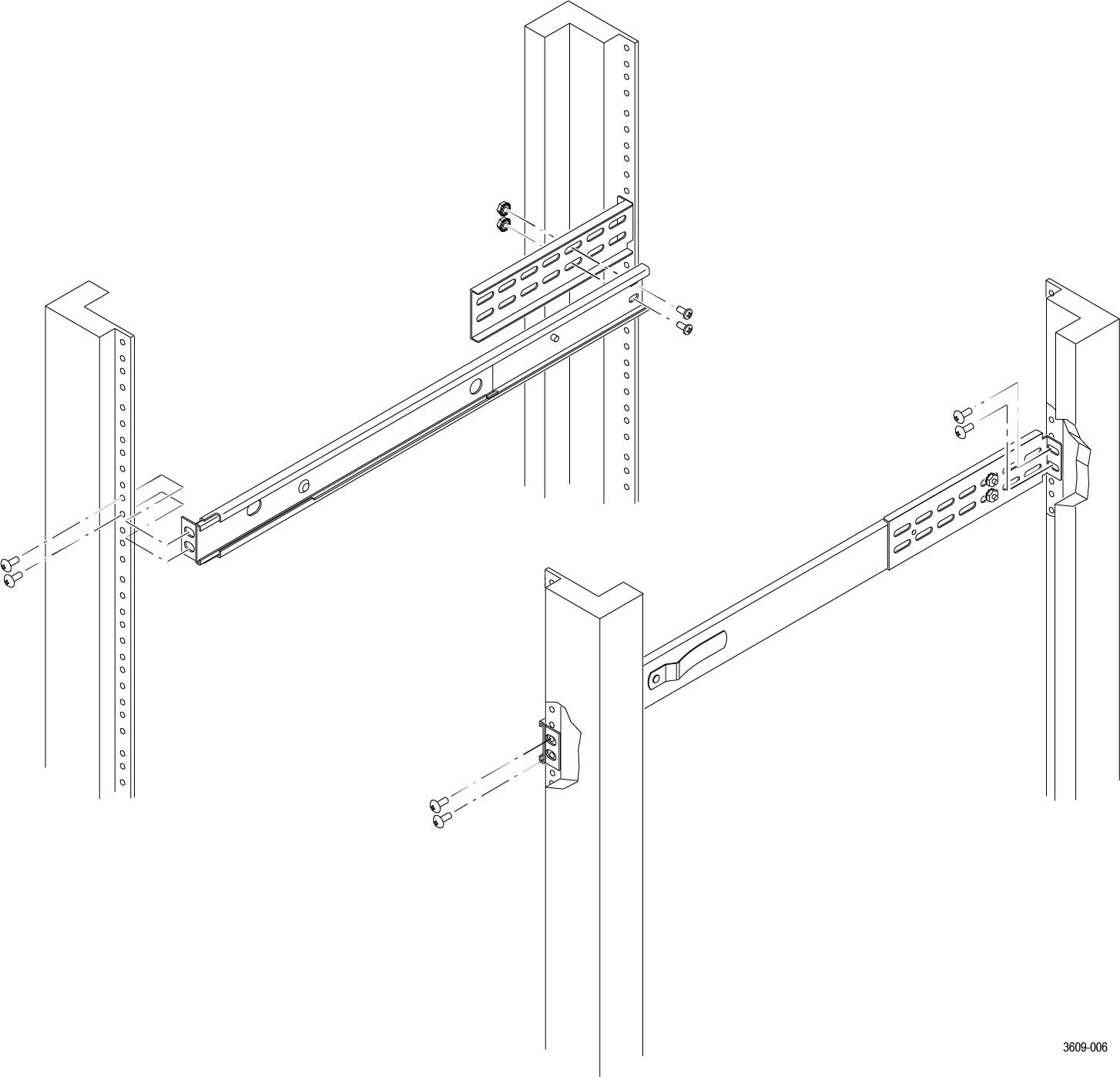
- Use the hardware from Table 3 to install the rack slides in your equipment rack.
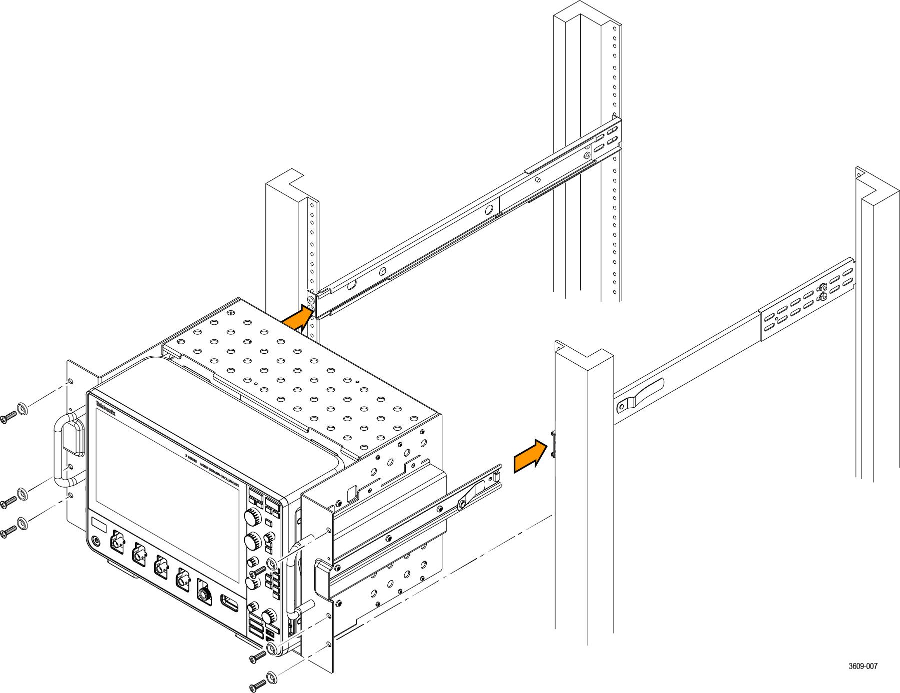
Figure 1. Installing the rail slides - Install the instrument in your equipment rack by inserting the rack mounts into the slides.
Figure 2. Installation of rack mounted instrument assembly into a rack WARNING:To avoid personal injury and prevent the instrument from tipping or dropping, use two or more people to install this instrument into the rack cabinet. After completing the installation procedure, verify that the instrument and the rack cabinet will not tip forward while the instrument is in the extended position. Do not leave the instrument extended when finished accessing the instrument. - Install the power cord. Provide access to a power plug or mains disconnect switch for turning the instrument on/off.
- Optionally install any cables you need connected to the instrument rear panel.
- Slide the instrument into the equipment rack, and secure the instrument to the rack using standard rack hardware.
Front panel dimensions
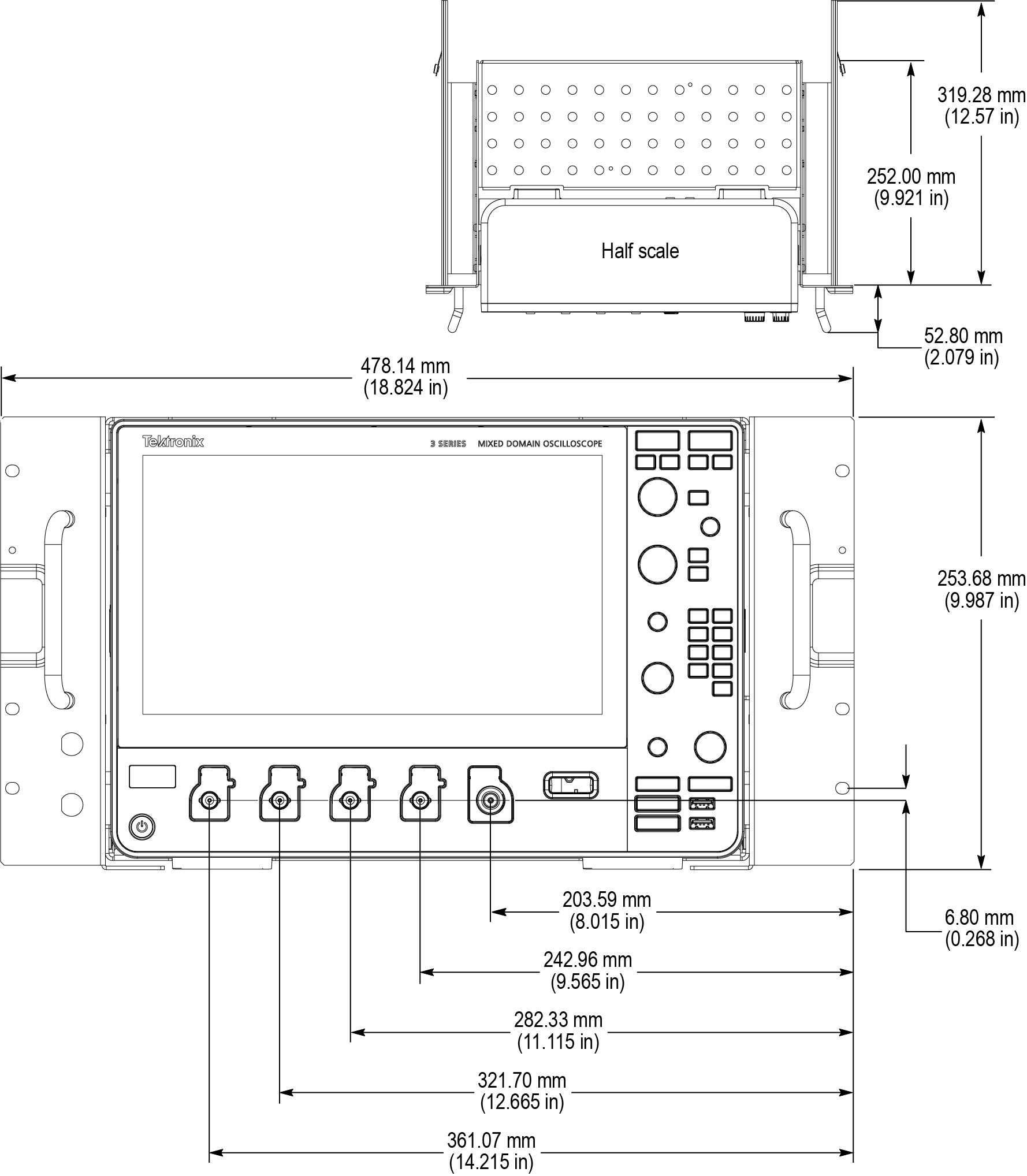
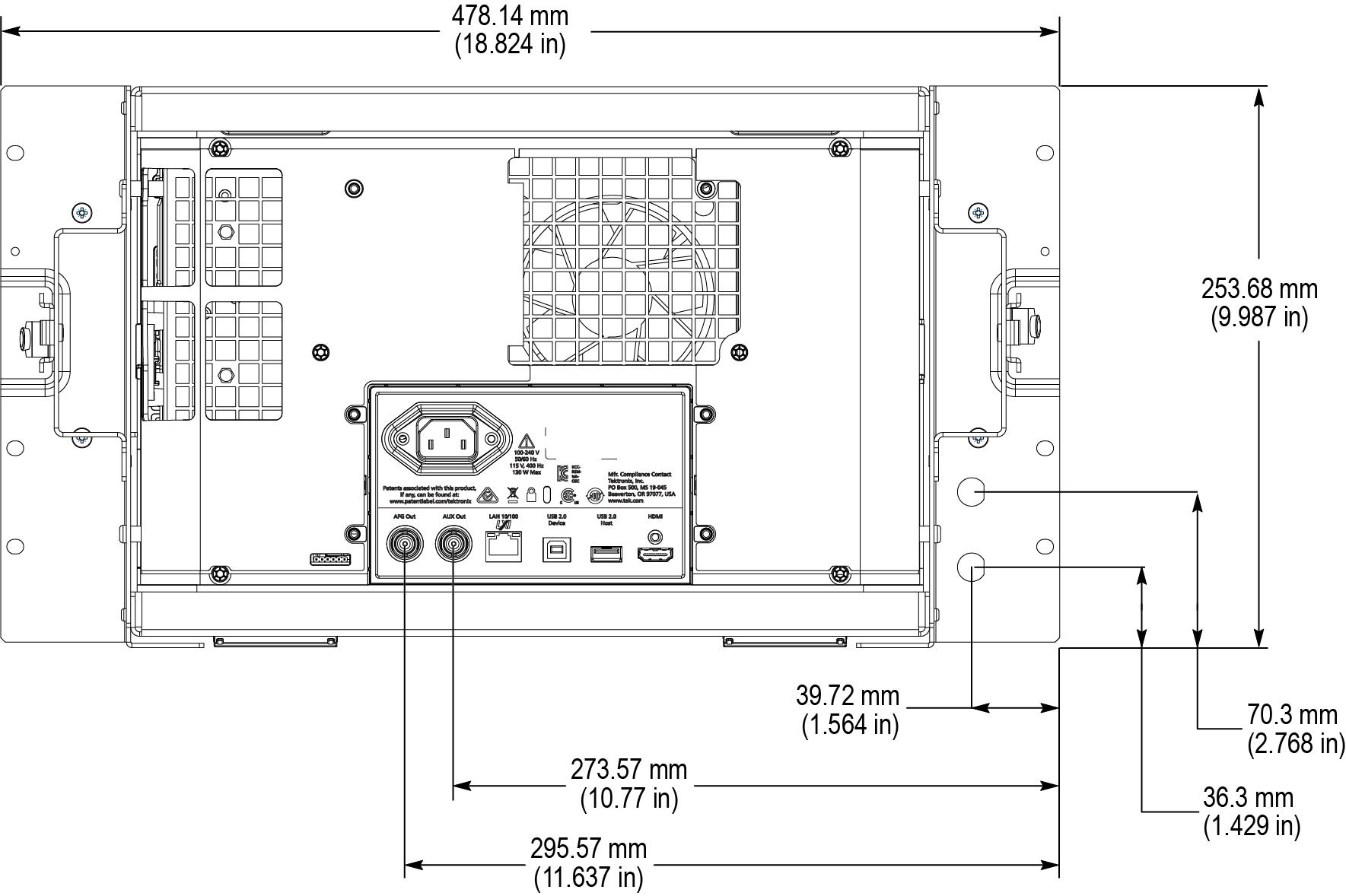
Rear panel dimensions